The Router Table: More Challenging Than Expected

It’s been a little crazy since my last post. I still had a few things I wanted to show off, I have my ever so beautiful router table (it’s definitely the work of an amateur…). I also made a nice cutting board for my girlfriend, so far it’s gotten good reviews. We’ll see if that holds, she’s only seen pictures!

Router Table

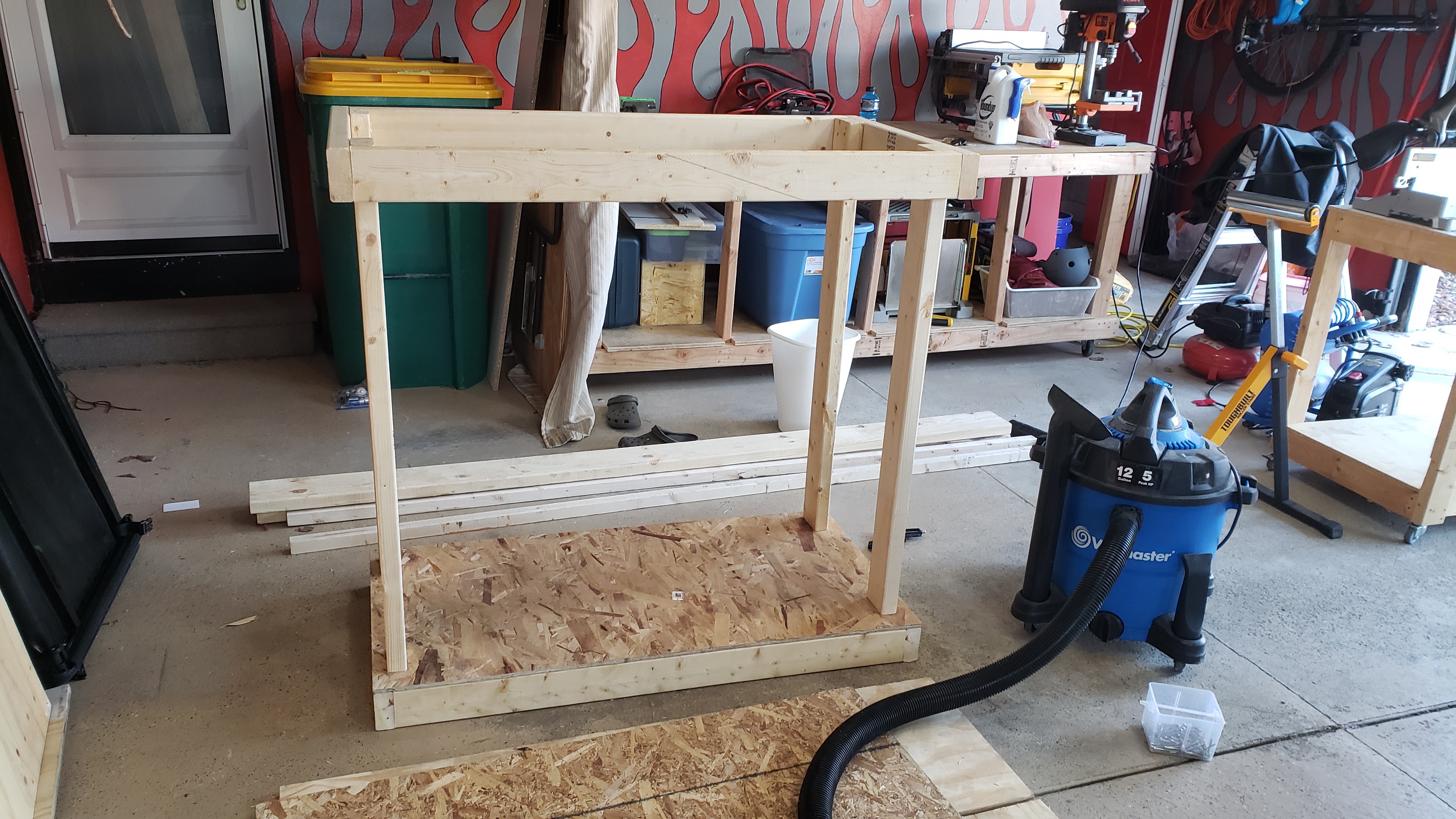
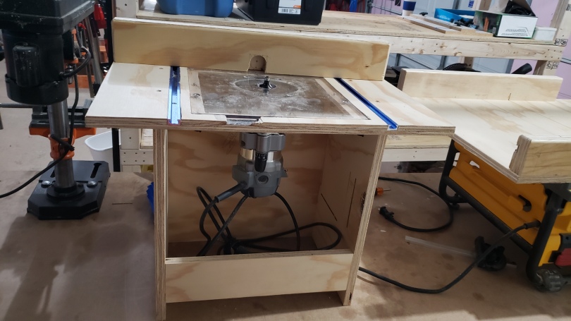
I eventually started getting tired of routing everything by hand, so I figured it was time to build a router table. This project was a little intimidating, because all the plans I was seeing on YouTube had cabinets and drawers, and fancy fences. I wanted something basic, I was surprised it was so difficult to find a basic one.

Eventually I found something basic, it was basically just drilling a hold through the top of the table, then putting mounting screws through holes in the top. They needed more than a countersink because the screws that hold the plastic router base are pan head and not flat, so a countersink wasn’t going to work great.

First Iteration – Router mounted on the underside

While this worked for the short term, it wasn’t going to be a long term solution. I wanted a better way to take the router out of the table if I needed to do freehand routing, because this way required unscrewing the router each time. I got a square piece of acrylic, removed the plastic plate it came with and mounted the square sheet to the base.

The Plan

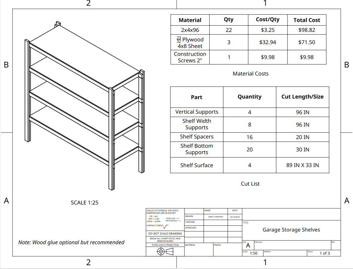
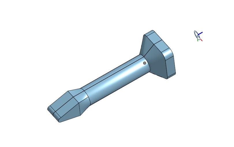
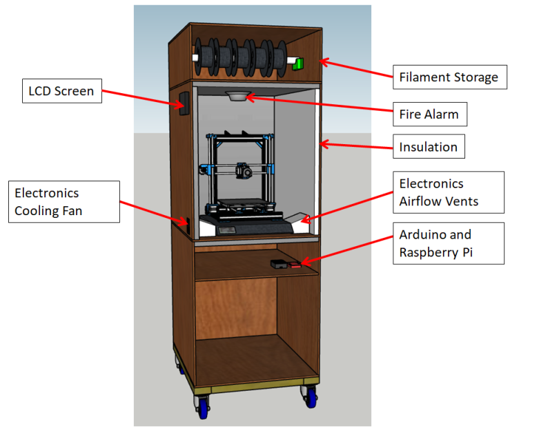
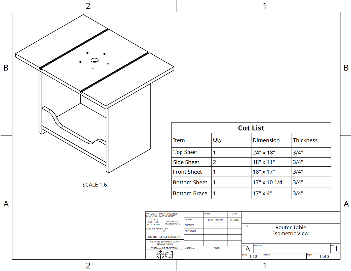
As I mentioned previously, I’ve started sketching everything out in OnShape. I like the drawings they put out and it gives me a good reference as I go through building something. I hadn’t modeled the acrylic as I hadn’t thought that far ahead with the design. Below was an initial cut list, it was a starting point.

I didn’t end up making the fancy curves on the bottom side support, I got lazy.

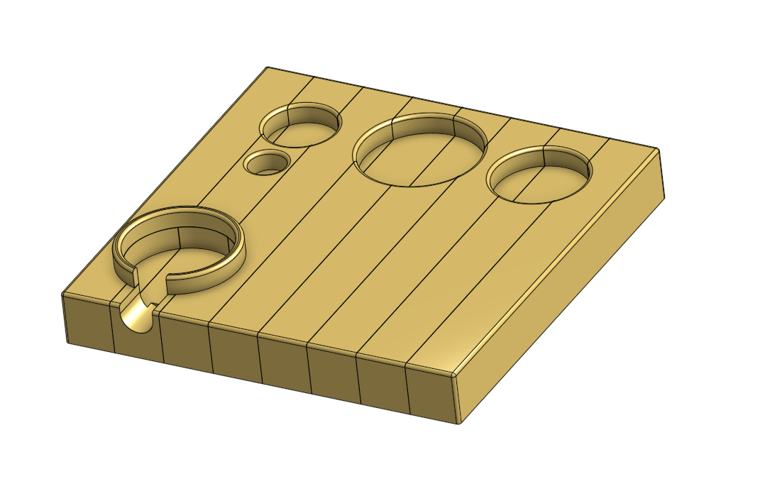
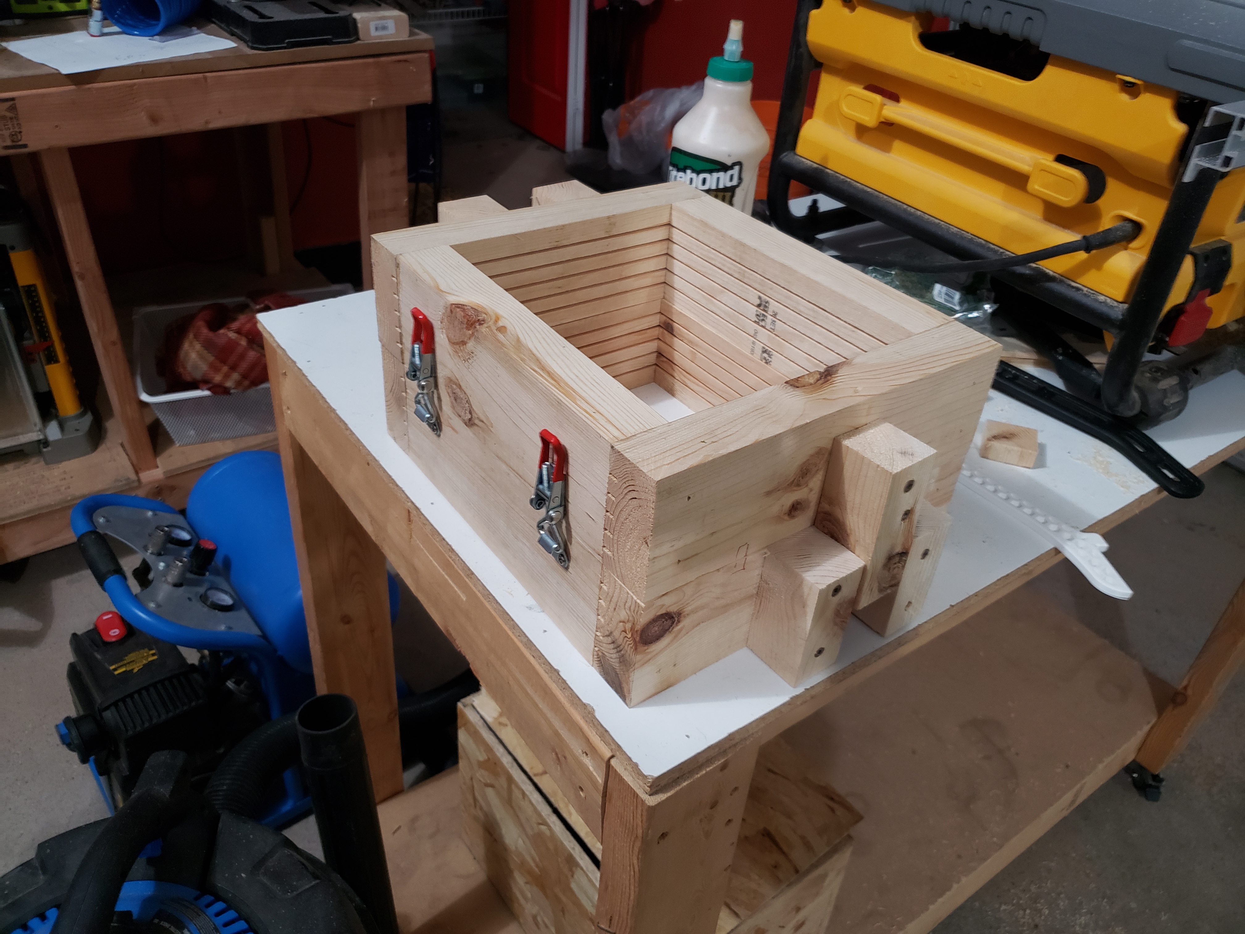
Cutting the Tabletop Hole and Landing

I decided to cut a hole out of the top surface, then cut a landing along the edge of the cut hole for the router to sit. I found a piece of acrylic that was just the right size, it was big enough that it allowed the full router to pull out of the top.

One thing I could’ve done differently is taken the hand holds off the side of the router, that would’ve meant the acrylic piece mounted onto the router could’ve been smaller. Always learning something…

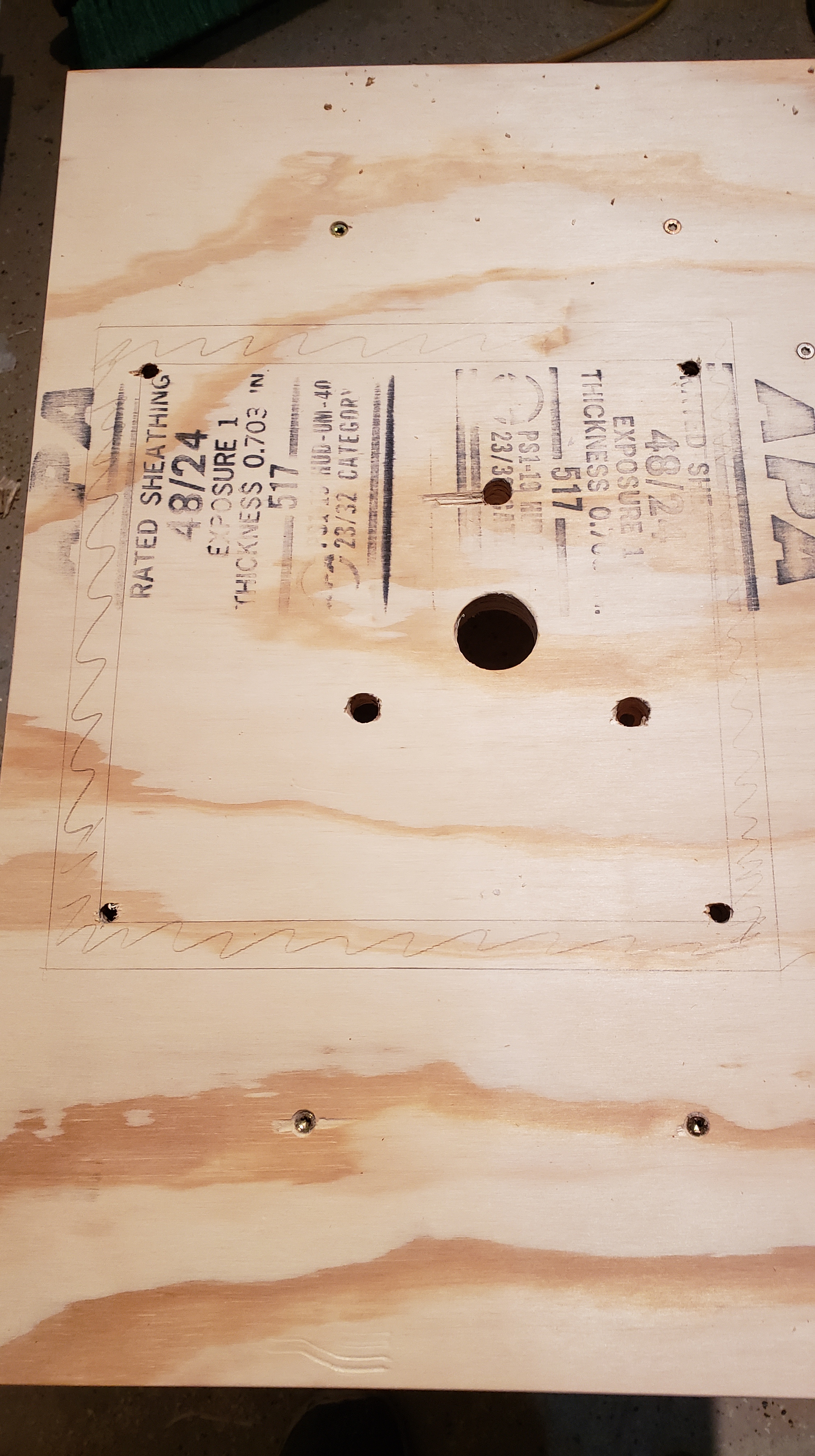
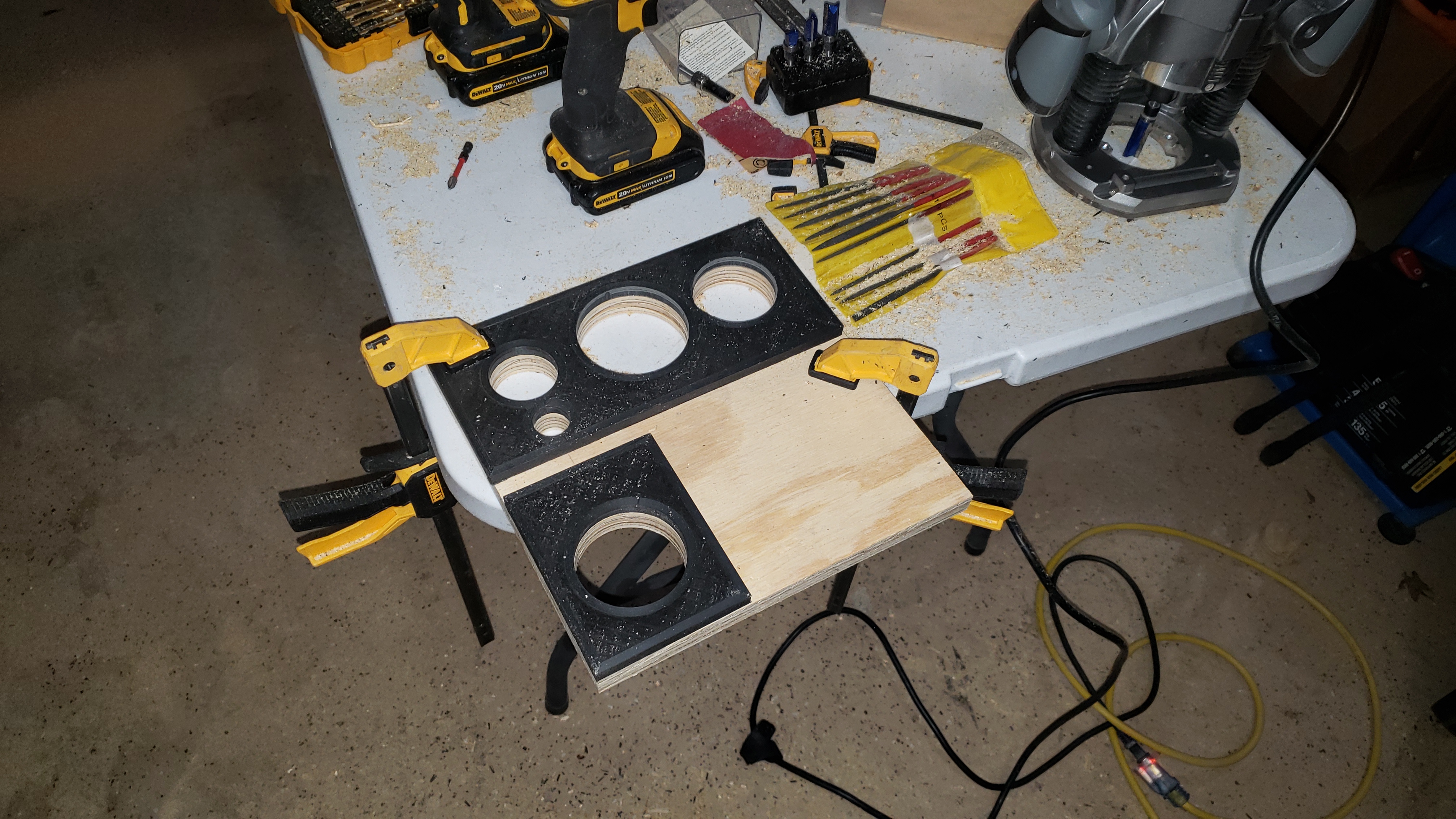
In the above pictures, the left hand side photo marked out the hole location as well as the step where the landing was going to be routed. I cut the hole out with a jigsaw, which didn’t give the most square finish, but it worked.

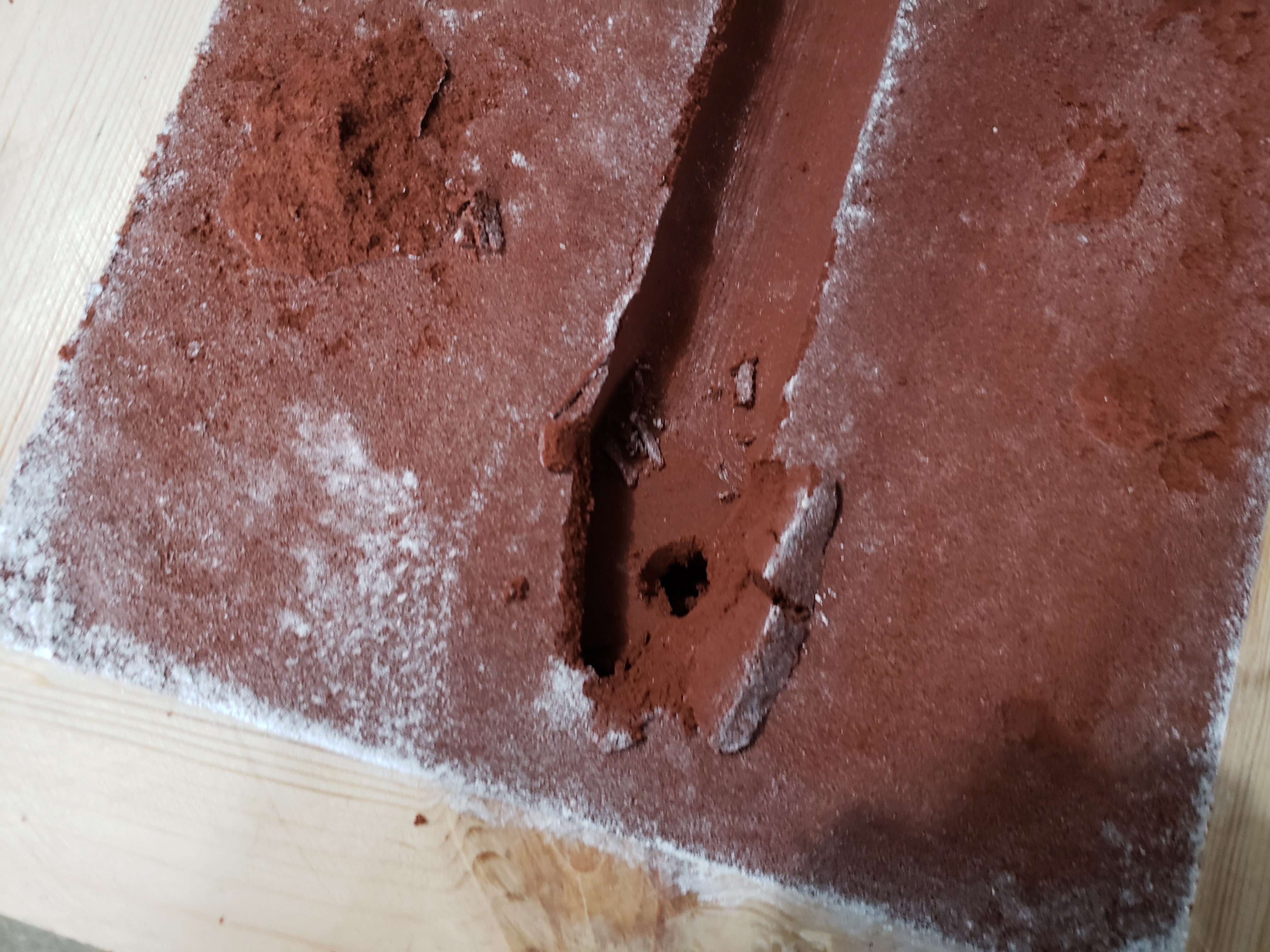
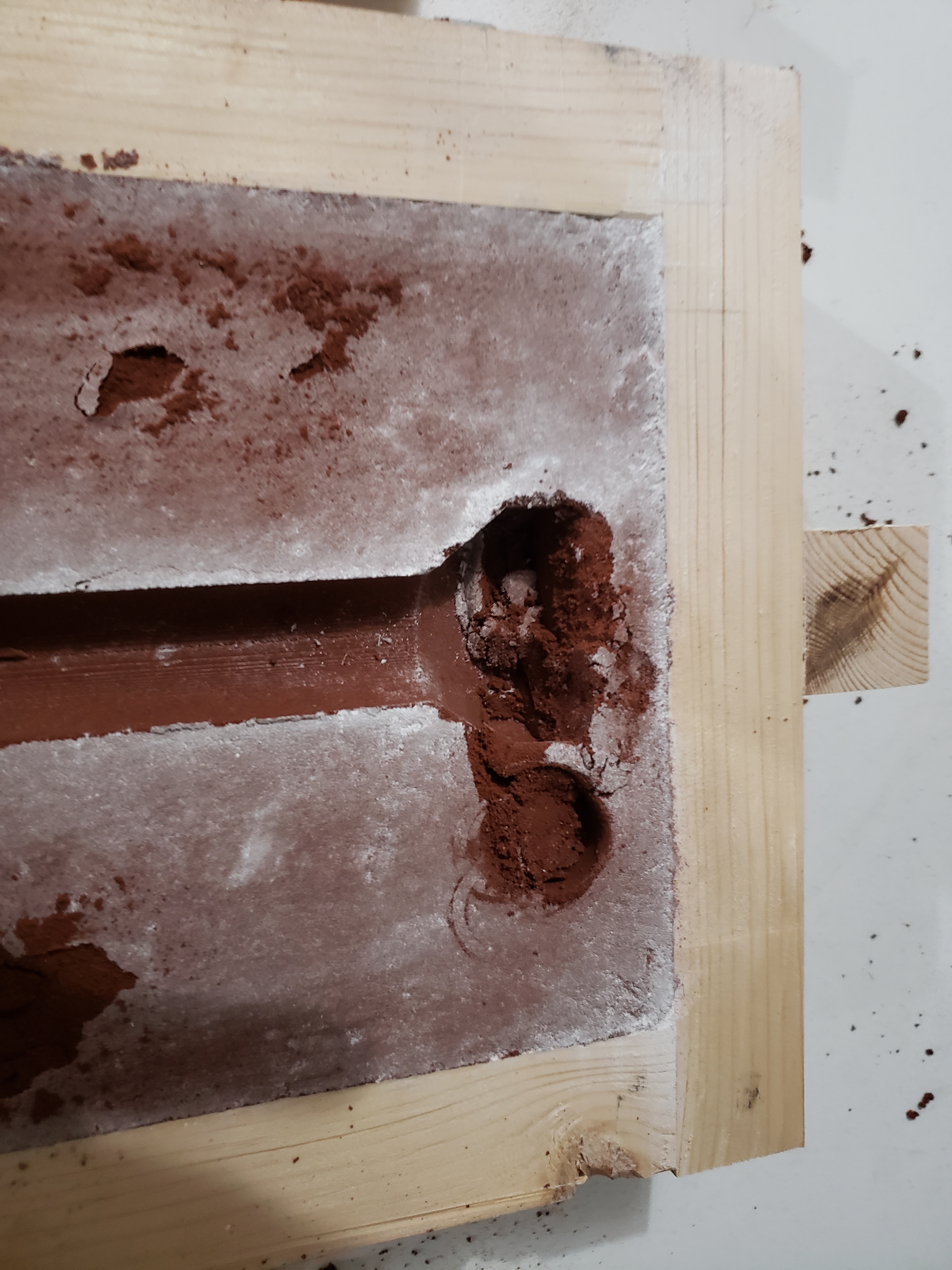
I royally screwed up routing the landing. I didn’t think it through entirely and used the outside edge of the tabletop as a reference for the router edge guide versus a separate guide which was parallel to the inside hole edges, which was a really bad idea. I spent a lot of time trying to get it perfect, and it came out looking like crap. I also had some chipping on the edge closer to the side of the tabletop.

It looks like crap, but I finally got the acrylic sheet to fit in the landing.

A close up of the step as I tried to get close to the edge of the marking
The Router finally fits in the landing. Note the nice chipout of the tabletop…

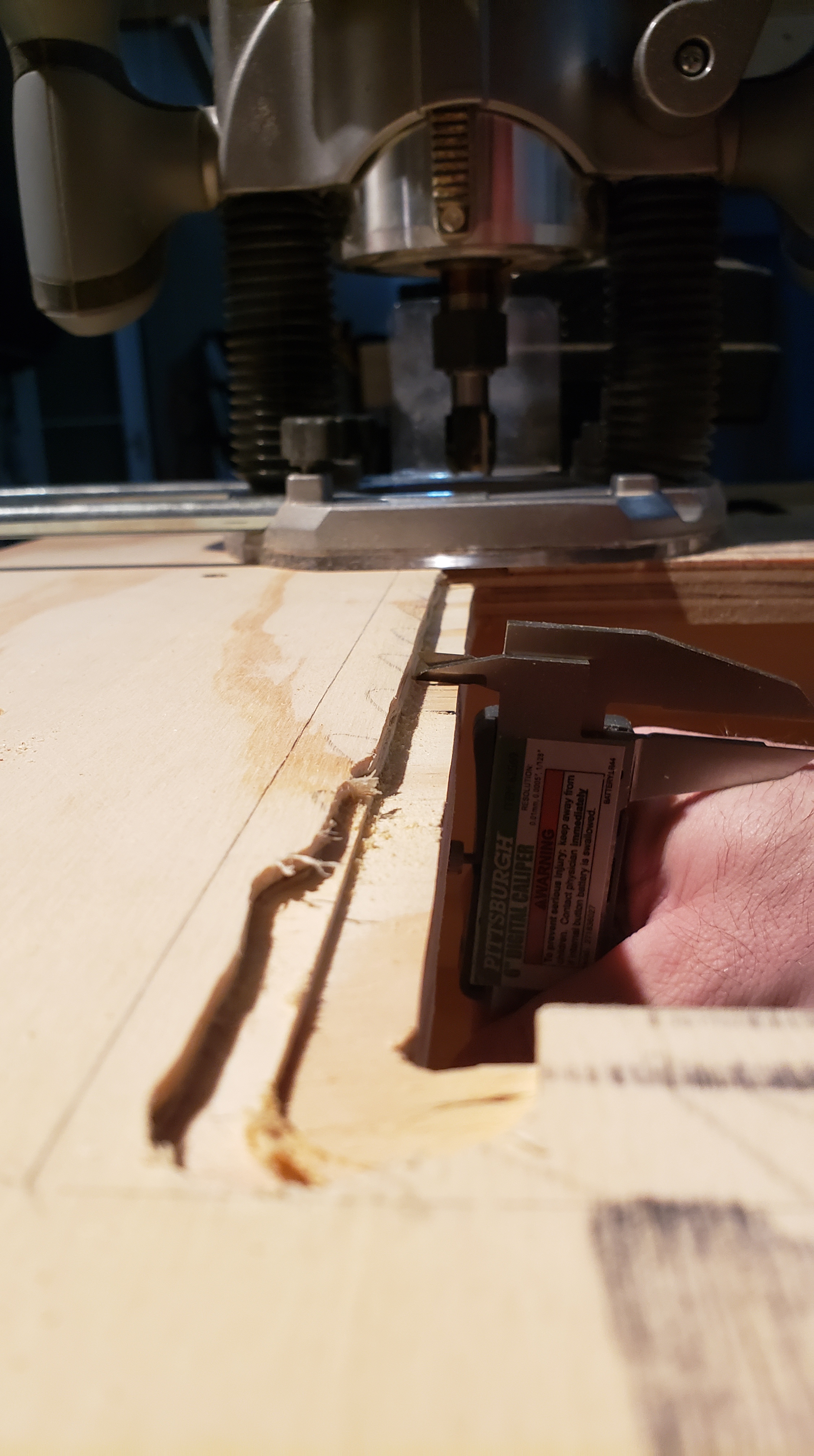
It’s hard to tell, but I made the landing a little deep as I planning to add adjusting screws around the edge later to make the acrylic sheet flush with the tabletop.

I added a number of adjustment thumb screws with inserts and added additional with steps for bolts that would secure the acrylic to the tabletop.

Dashed Circle: Thumbscrew – Solid Circle: Bolt Holding Down Sheet to Table
Acrylic is Flush to the Table
Thumbscrews allowing Adjustment of the Acrylic Surface

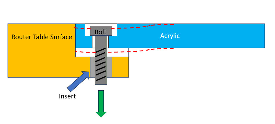
One of the issues I ran into with routing the step lower than the edge of the surface was that after adjusting the thumbscrews to get the acrylic flush, the fasteners that hold the acrylic on would bend the acrylic downwards near the bolt. This basically eliminated the adjustments the thumbscrews were doing.

Below I sketched out a cross section of the acrylic to demonstrate what’s happening. As the bolt tightens down on the acrylic surface, it pulls it down, preventing it from being flush with the tabletop surface.

This was one of the issues with using the acrylic sheet, it flexed more than I thought it would. With the weight of the router base and the size of the hole, the acrylic sheet sags in a little bit. Something I plan to do in the future is add some gussets or ribs on the underside to stiffen the acrylic sheet. Other thing I might do is just get rid of it altogether and use a thinner sheet of plywood instead of acrylic.

I found that when I adjusted everything, the vibration from the router would cause the thumbscrews to loosen themselves out of the inserts. I have some loctite purple (low strength) I plan to use to keep the thumbscrews in place once they’re adjusted.

Adding some Rails and a Fence

While it worked fine once we got to this point, I wanted to add a fence. This would allow me to make straight slots, groves, or any kind of routing action that could use a fence support.

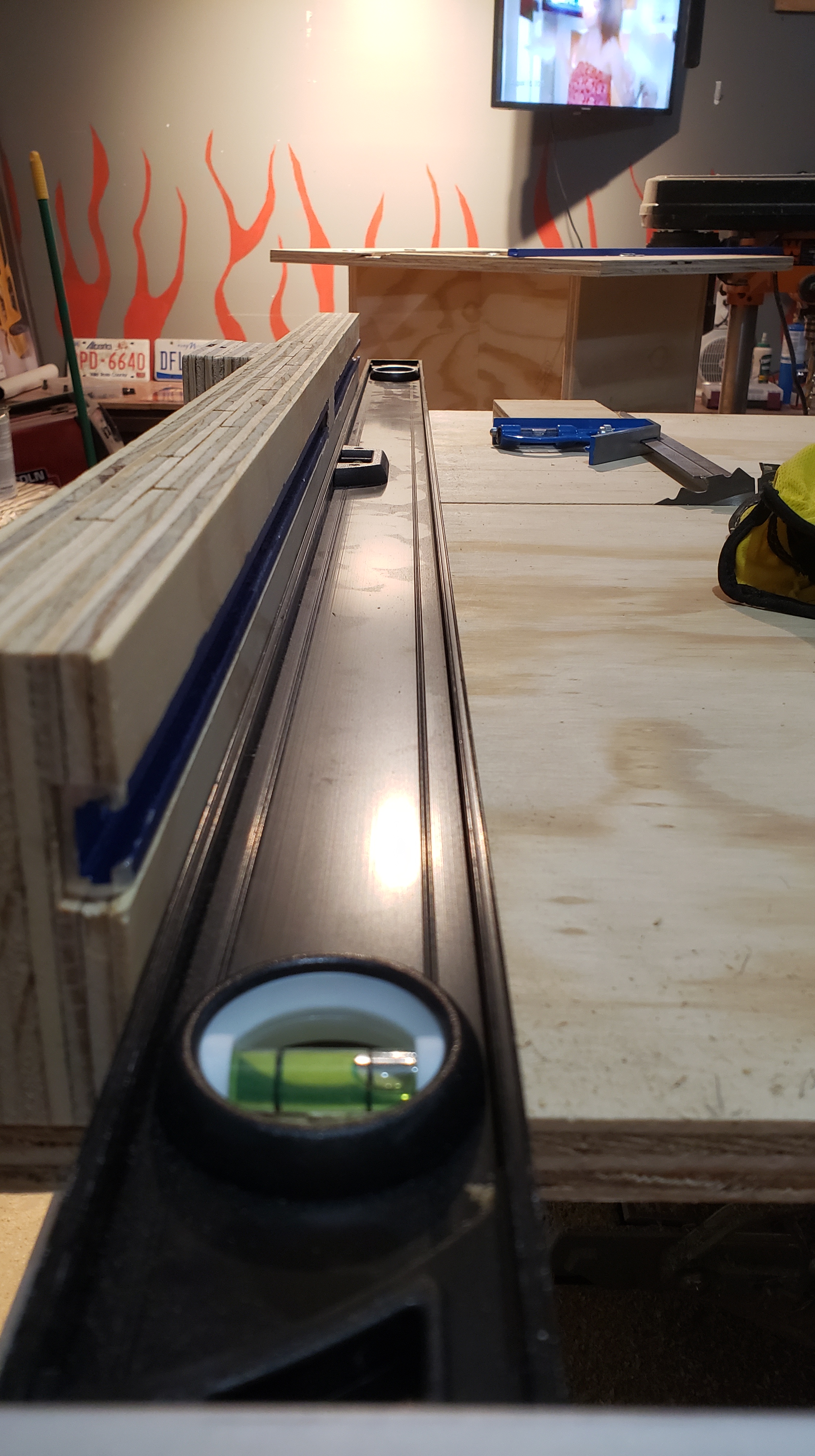
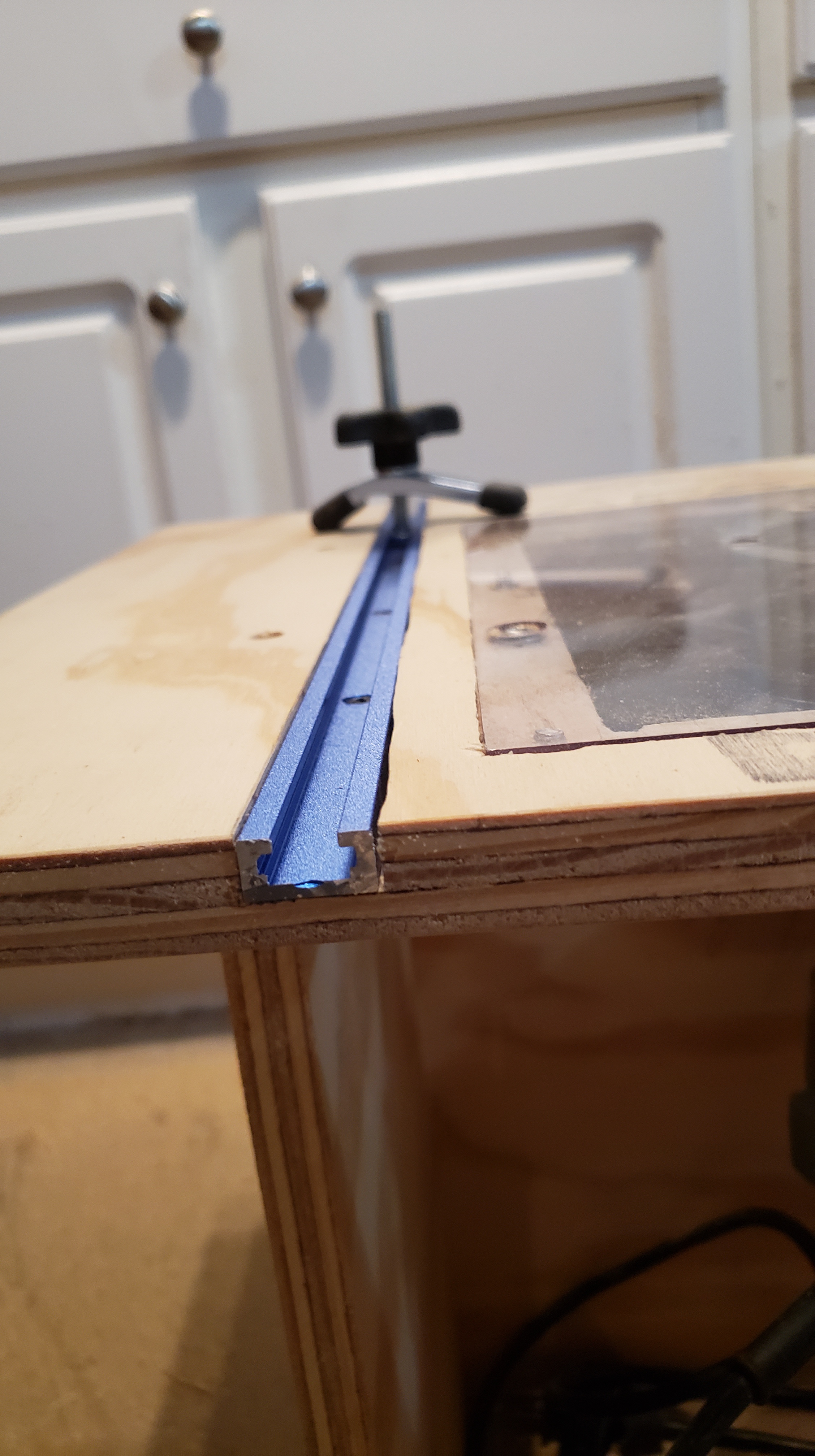
Learning from my mistakes with the landing, I clamped a piece of t-track to act as a reference edge for creating the t-track slots. This went a lot better than the landing.

Slot Cut for the T-track
T-Track Installed

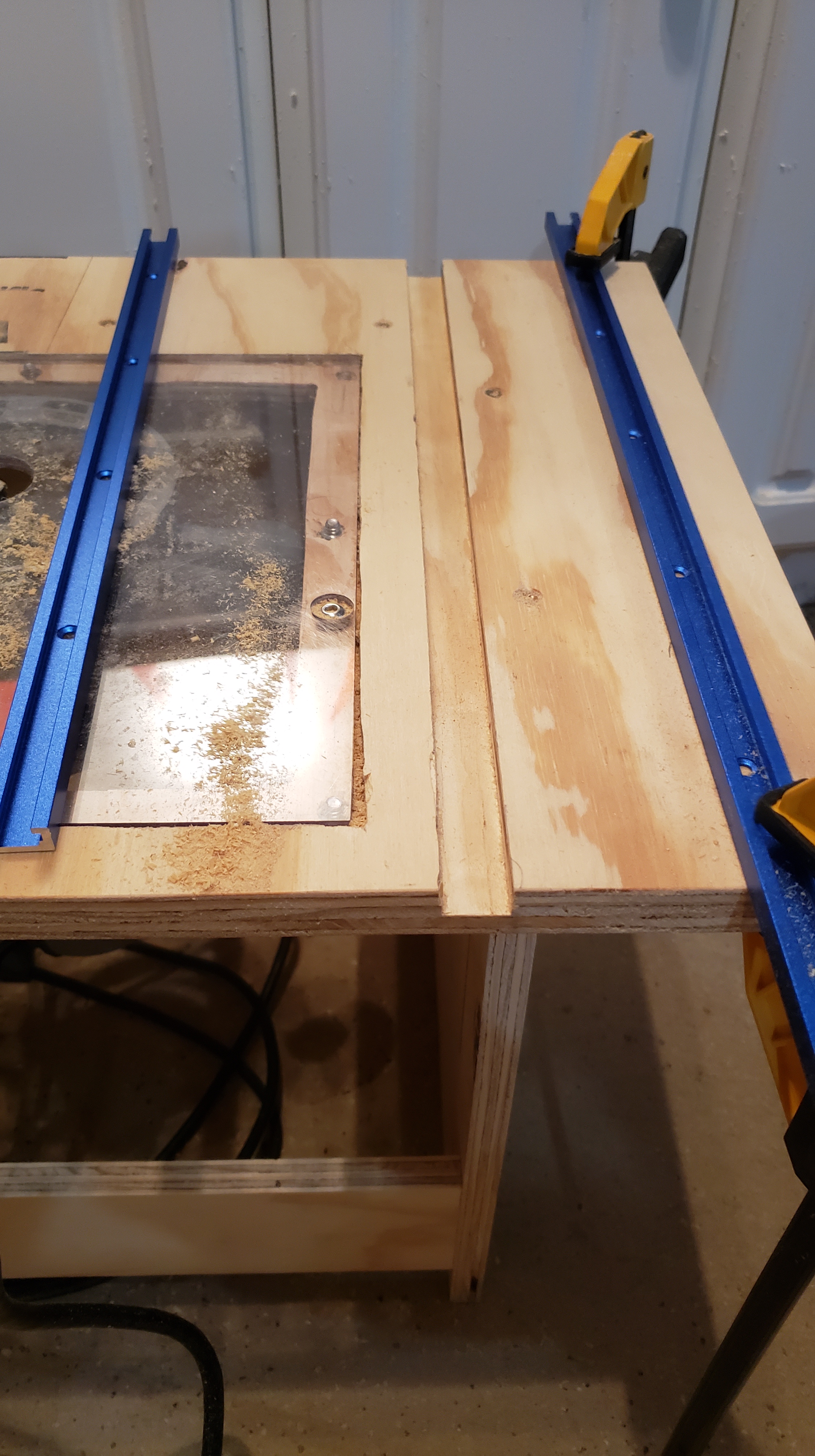
With the T-track installed, all that was left is the fence. I glued up a few pieces of plywood into an “L” shape, cut some slots into the back for the t-track bolts to go through, planed the surface near the bit to make it flat, then drilled out a section for the router bit when the fence was in place.
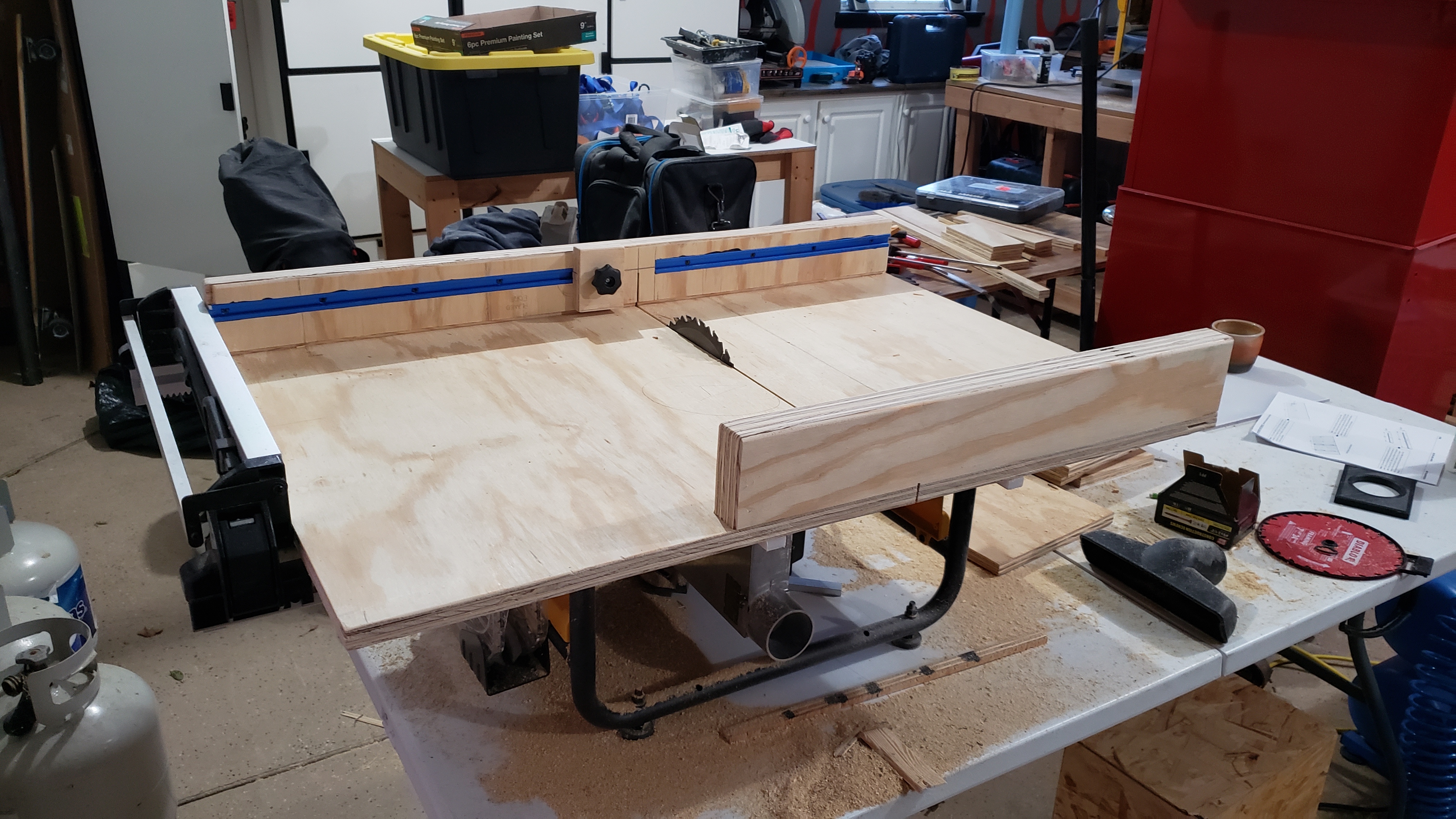
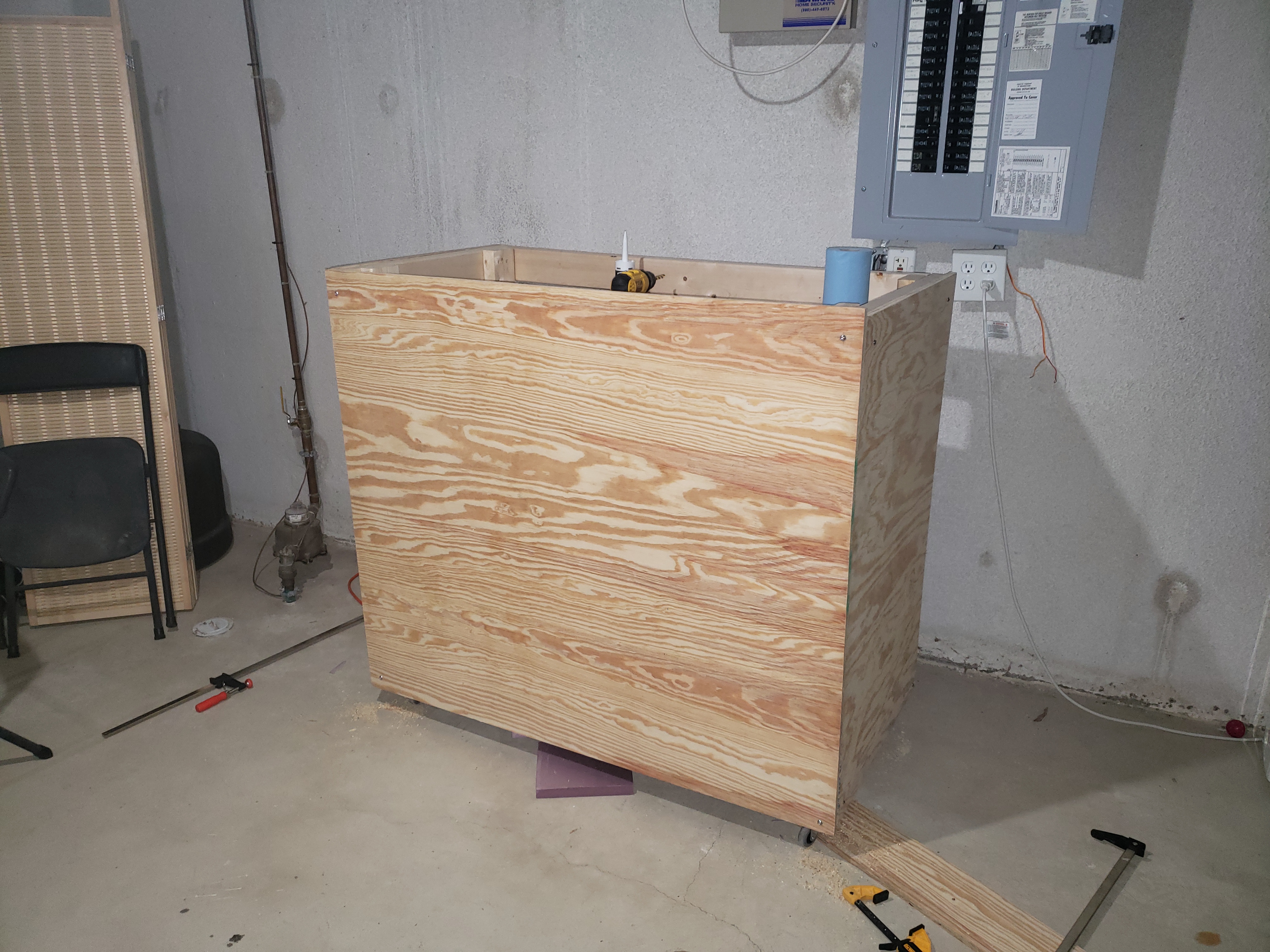
The Final Result

While it didn’t look exactly like the plan I had started with, it works pretty well. It’s going to make my life a lot easier when it comes to routing.

Since I can’t leave anything alone, I do have some planned improvements.

  • Add Loctite to the thumbscrews to prevent them from backing off
  • Add support pieces underneath to stiffen the acrylic structure
  • Modify the fence for dust collection, wood dust builds up quite quickly when using the fence

Lessons

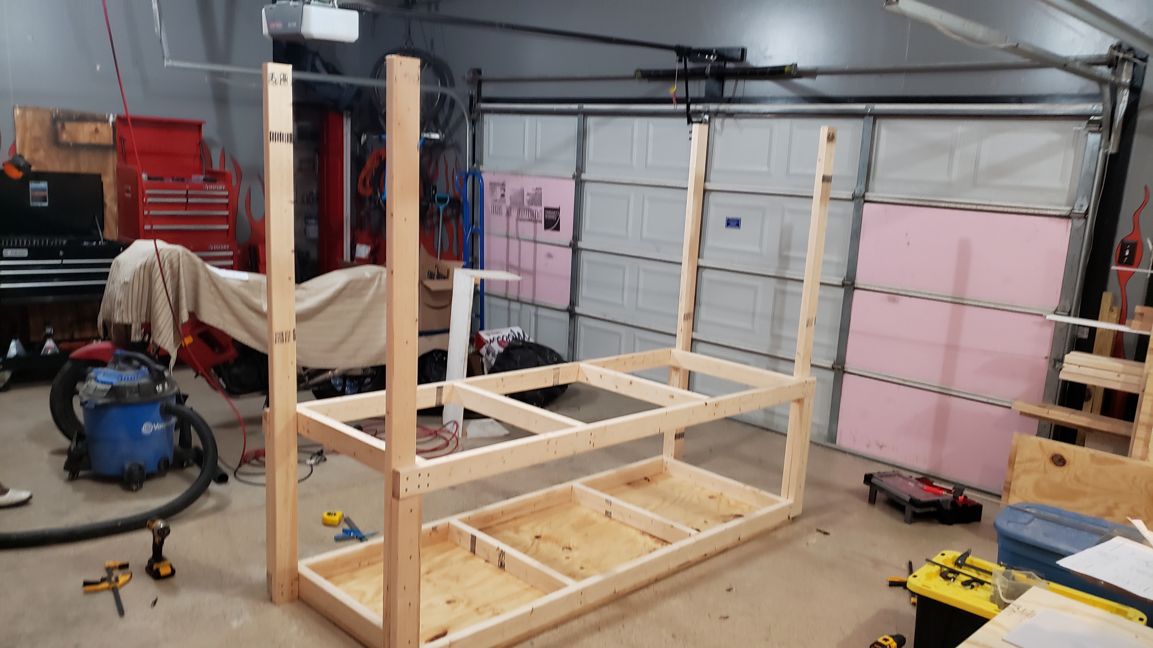
I built this using existing plywood sheets, so if you need something basic and quick, it’s easy to make something work.

Cutting the Landing

As I mentioned earlier, I did a really poor job of this, partly because I didn’t have good references for cutting a straight line at a specific depth. Even though it works, it doesn’t look very nicely cut.

Landing Depth

I didn’t need to make the landing depth as deep as I did, as I discovered how much the acrylic would flex when bolted to the plywood tabletop. In the future, I’ll probably just cut it a little lower than flush, and adjust the thumbscrews as needed.

Using a Router

Whenever doing router cuts, it’s better to make small passes and adjust rather than try to take off too much all at once. Maybe once I get better at it I’ll be able to make deeper cuts once, but I ended up with too many issues cutting too deep when I try to cut too much from the slots.

Chip Out

Going forward, if I’m concerned about a surface chipping, I need to start putting tape over the area to try and control the chip out, it’s been happening lots lately, and it’s hard covering up chip out once it happens.
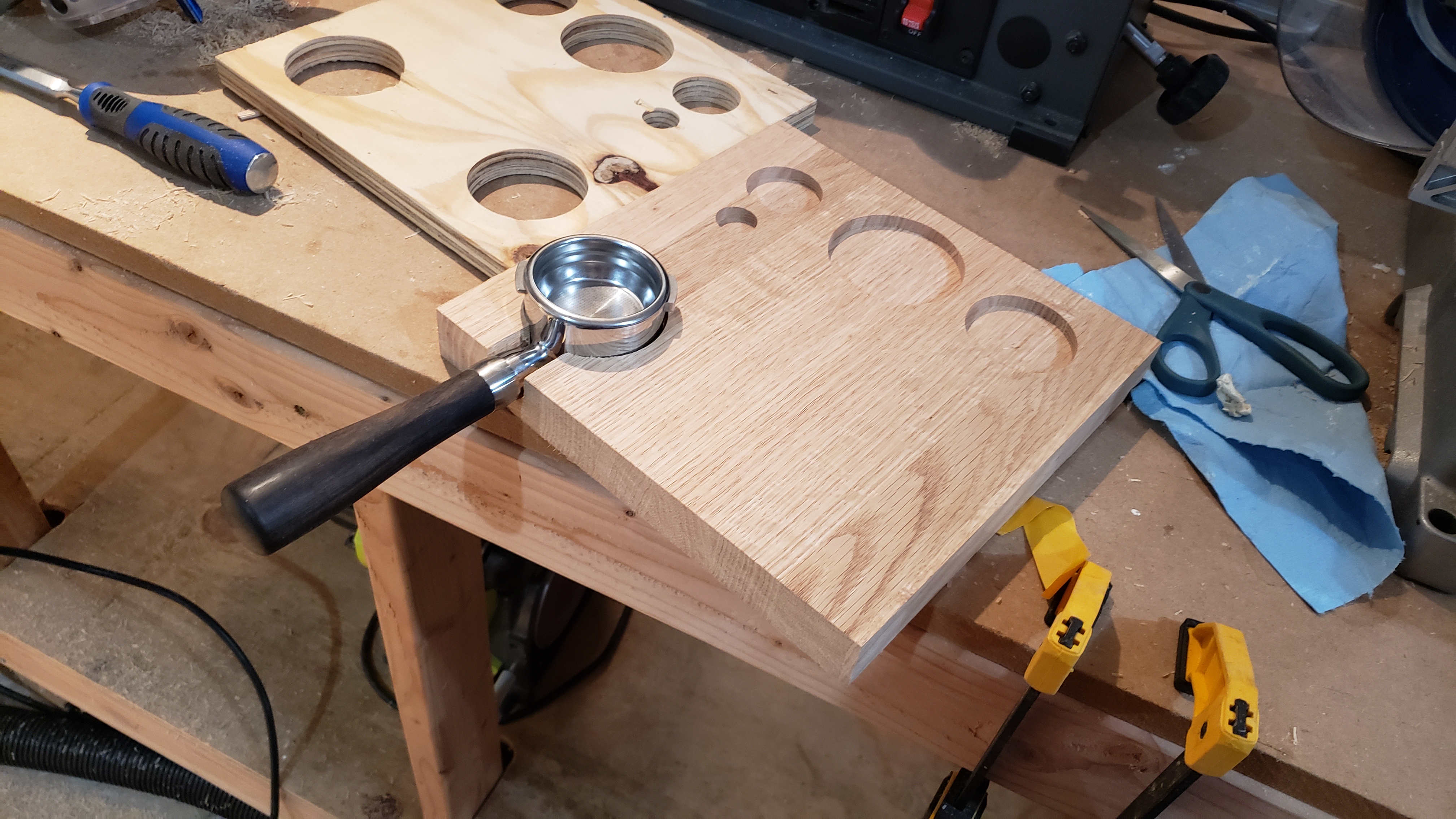
More Cutting Boards

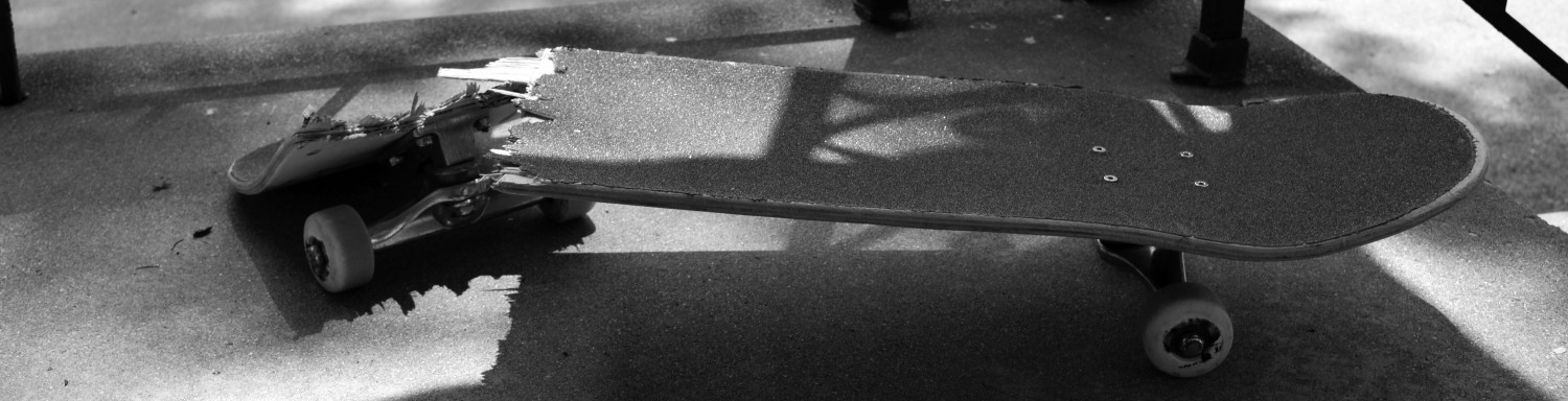
I had some additional oak laying around, and now that I had my router table somewhat figured out, I thought it was time to make another cutting board. This one was quite a bit thinner than some of my other ones, I didn’t have a much usable skateboard deck strips to work with.

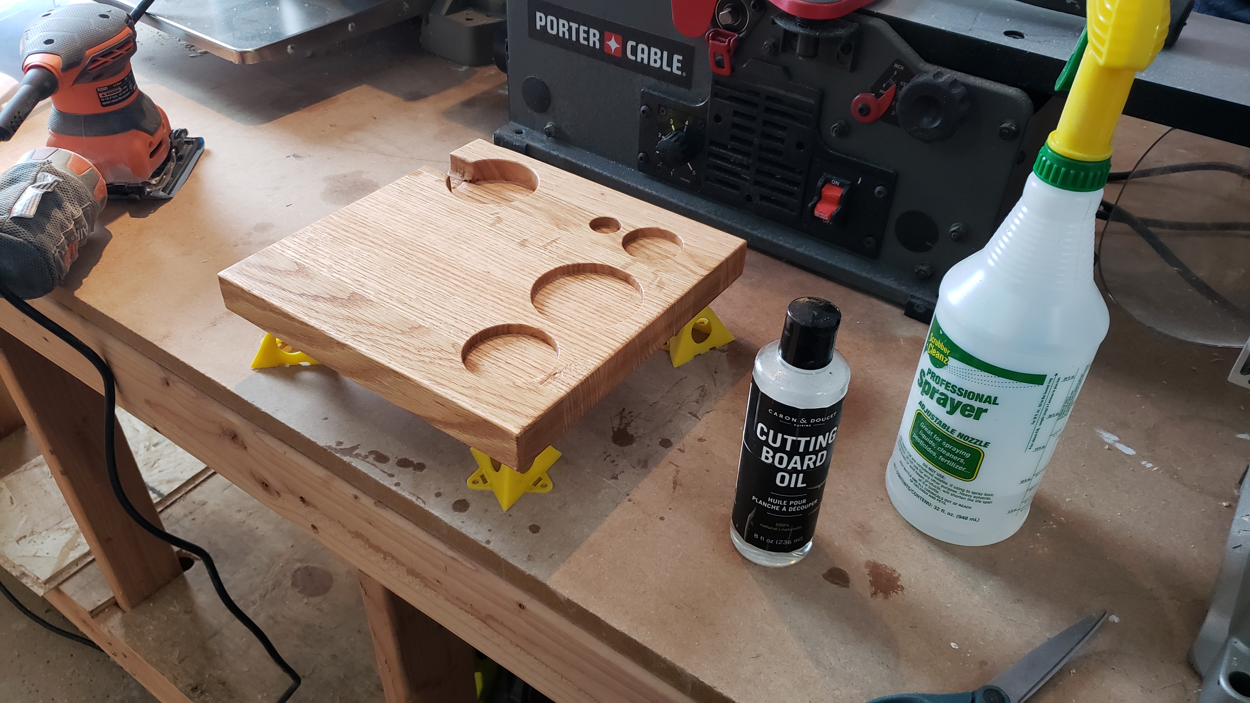
This time I decided to try and route channel along the edges, more as a drip guard for liquids. As expected, things didn’t go quite as planned. You can see in the picture below that I got burn marks in the channel, this is a mix of things when cutting the channel out. Next time I’ll have to move a little quicker and adjust the router speed to prevent the bit from burning the wood. Otherwise, I really like how the oak contrasts with the maple when you add the cutting board oil.

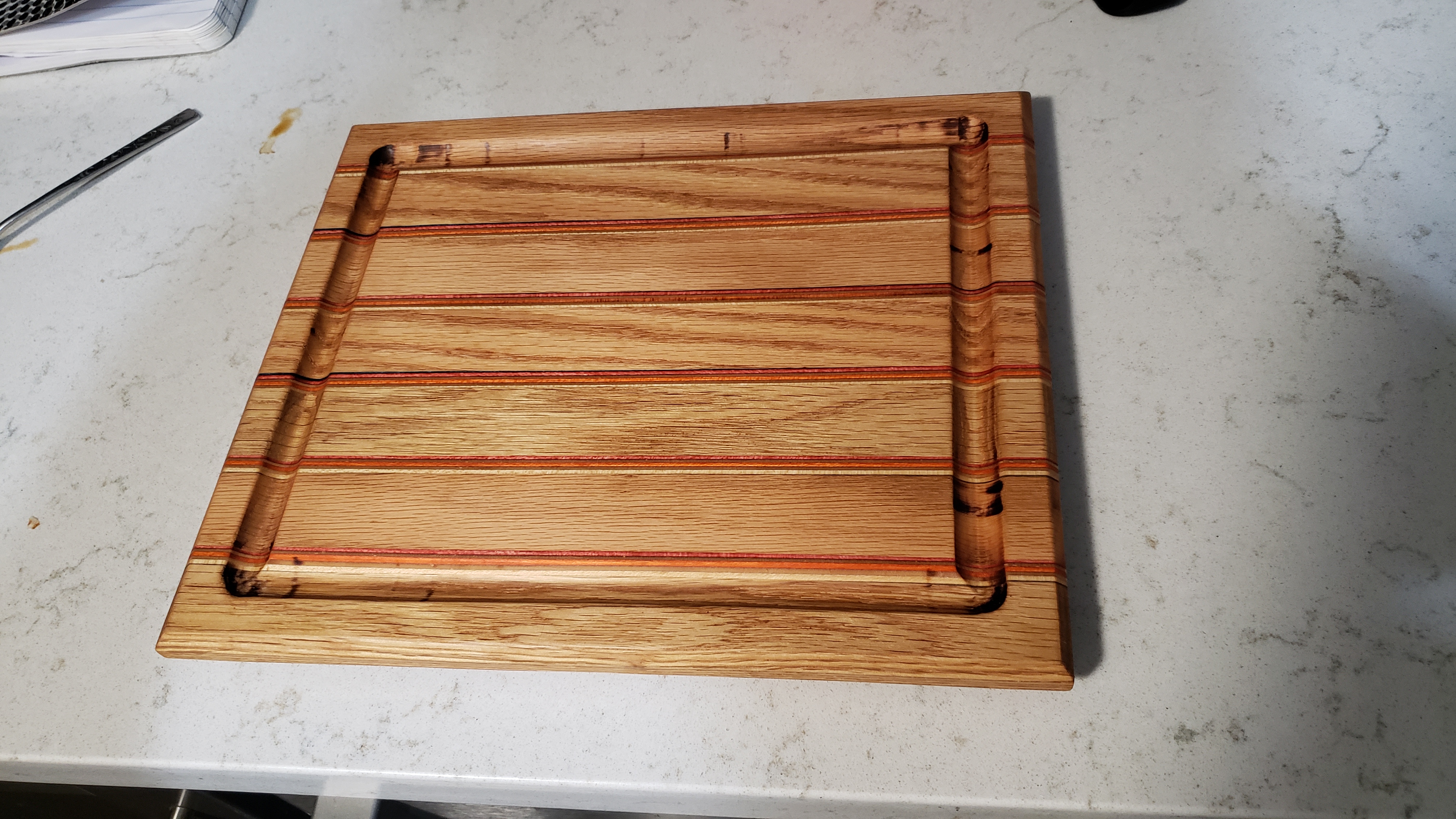
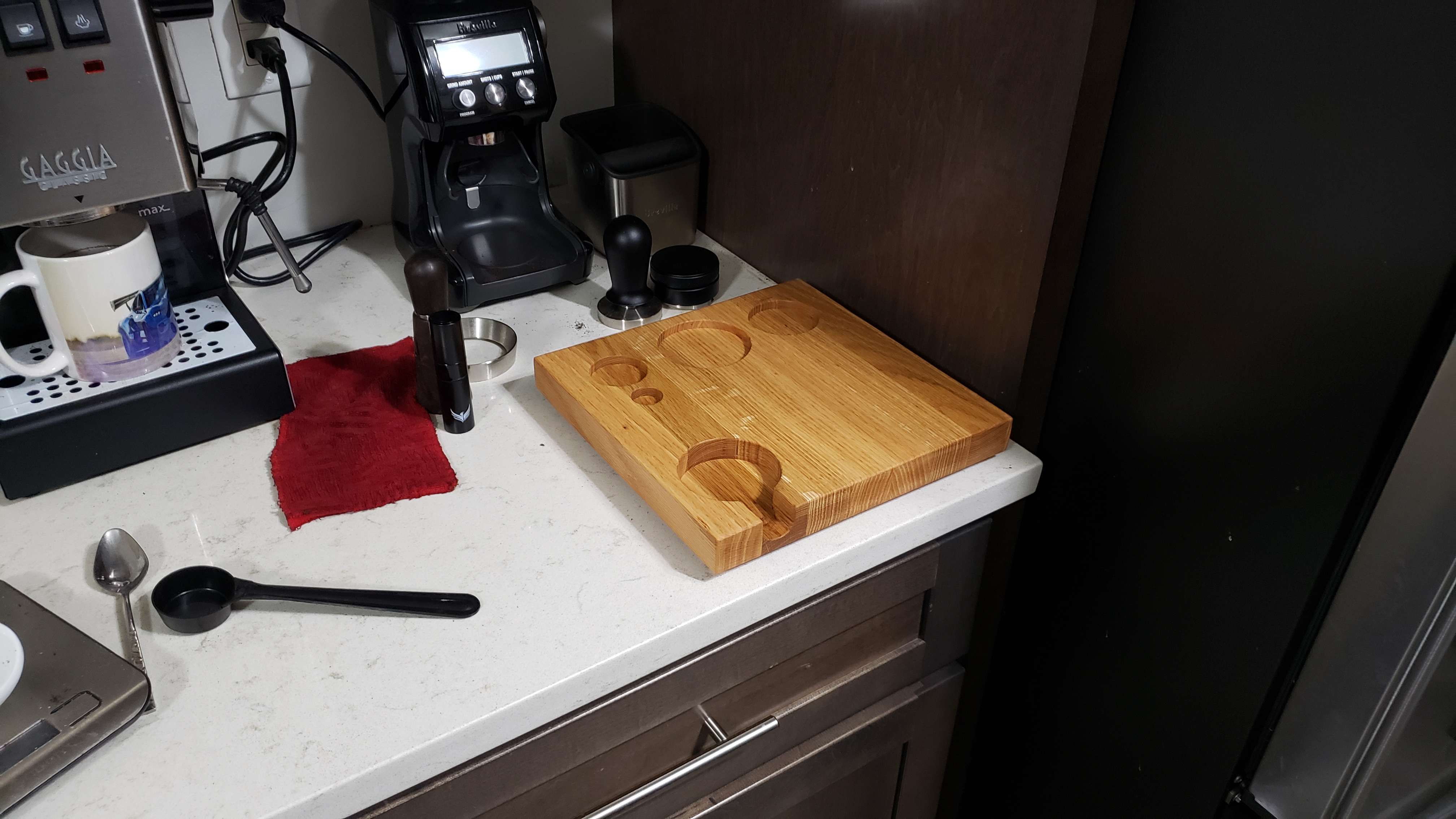
When you compare this against one of my earlier cutting boards, you can see how much smaller it is. This is nice as it’s not nearly as heavy as the maple cutting board I made.

What’s Next?

Aside from woodworking, I recently went to New York for the first time, oh my what a city that is. I’ll probably plan on doing a little writing on that city. Times Square was a little overwhelming to say the least.

I do have a lot more projects planned, it seems like there’s never enough time to work on everything. I have yet to figure out where my priorities are when it comes to my hobbies, I’m stuck between woodworking, electronics, golf, skateboarding…I’ve stretched myself a little thin!

More to come soon. Thanks for reading!

Woodworking: New Tools and Space Organization

Last I left off I’d finished making my espresso buddy to help organize my barista space in my kitchen. There’s certainly been no shortage of lattes made in my house! I still am not superbly consistent, but at least I’m starting to get some nice looking leaves, or some hearts. I still have a lot to learn on how to properly pour once the milk has the appropriate micro-foam, but at least I’m making some progress.

Woodworking

After I finished the espresso buddy, I wanted to improve the accurate or squareness of some of my cuts. While I had a method of getting nice flat pieces for glue ups on cutting boards, I wanted an easier way to make square cuts. I found my current table saw miter slide wasn’t really doing the trick.

It’s finally time for the crosscut sled. This one intimidated me because if it’s not built properly, it completely negates the purpose of it’s function. It’s binds up in the slots of the table saw, doesn’t move well, and doesn’t cut square.

I used the following set of plans from Fix This Build That. It was simple enough that it would work for my purposes, but also had a T-track slide that allows for a stop block to do repeated cuts at the same length. I’m not going to go through step by step how I did this, the plans in the link do better justice than I can. I’ll just go through the lessons I learned.

My beautiful crosscut sled.

Squaring the Fence

In order to get square cuts on the sled, the fence needs to be squared (this is the piece that has the stop block and blue t-track. This was a rather frustrating experience, I needed to make very minor adjustments to get the fence square.

It took a while, and I ended up making a second fence as the first one was bowed ever so slightly, but I ended up getting it 9 thousands of an inch squared, or 0.009″. To understand what this means and how I squared it, this video shows the 5 cut method to making a crosscut sled square. It took me way too long to figure out that I was doing it backwards, hence my cuts were getting worse the more i tried…

I learned a few things from building this.

  • I used plastic/cutting board material for the runners on the bottom, when I screwed them down they were ever so slightly out, enough to cause binding. I sanded like crazy to get them to move somewhat smoothly. Supposedly there’s a trick that involved marking the runners with a pencil then moving along the track to see where the runners are binding, then sand that area. I found that didn’t really work with the plastic, the graphite of the pencil didn’t really mark well.
    • I managed to get it working, but it doesn’t move as smoothly as some do on youtube. It works for my purposes

All in all, it’s a great tool to add to my woodworking arsenal. In my next post I’ll cover my router table, it went through a number of iterations, and will likely go through a few more, I’m still not happy with it.

Garage Organization

One of the biggest issues I’m facing at the moment is trying to keep my garage organized for multiple project types. While I have a larger space to do work than I did before, it’s still challenging to separate organize, everything I want to do needs space! Woe is me 😦

I’ve tried to separate things by type, so I have a woodworking section, and an automotive section. Still not sure where metalworking will go, but I’ll figure it out in time. Below is my garage sketched out.

To help keep things sectioned, I needed a bit more storage for my woodworking tools, it was getting hard to keep them organized in the cabinets I have to the far end of the garage. Hence, I decided I would build my own shelves from 2x4s and plywood. I could make them the size I want and while there’s some labor, it would be larger than the home depot garage shelves, and cheaper. The only trade off is that they can’t exactly be disassembled, so they’ll stay with the house pretty much forever.

The red box is where the shelving will go.

I modified plans that were based off Bear Mountain Builds shelving plan for home depot crates. All in all, it wasn’t too bad, it just too some time to put everything together. I had to modify the plans so that I could put wider crates and tools on the shelves, as well fit underneath the track of the garage door.

Storage shelves complete and serving their purpose.

So far it’s working well, I can keep things a little more organized.

Planning Out Projects

As I’ve mentioned in the past, I typically need a solid plan or set of plans/drawings before I start on anything. I typically have to make adjustments as I go, but the plans help me visualize the end before I get there.

I’ve been using OnShape to put together my 3D models and drawings. I can also export the 3D models for use with my 3D printer. This is how I made the circle templates for the espresso buddy in the previous post.

Below are some examples. The drawings are very far from engineering standards, but it helps me visualize and plan things out. One thing I’d like to get better at (even if it takes time) is getting screw, bolt and fastener locations on these models.

The router table and the small stairs I’ll be covering in a future post.

What’s next?

As mentioned above, I’ll be covering a few additional woodworking projects, the router table and the small stairs. At some point I’d like to get back into some projects I’ve abandoned, like the 3D printer cabinet. It’s likely to get modified as I ended up using the built in shelves in my basement for the printers, so it’s really a matter of enclosing the space safely. I’m due for some 3D printer calibration as I’m having some edge lifting and surface quality issues, but that’s a long topic for another time.

Thanks for reading!

Time to Organize the Espresso Making Accessories

Note: I have some links to products I have or used for this project. I don’t receive any compensation if you click there, they are just there purely for reference.

Ever since I moved into my new house, I’ve come to really enjoy my morning routine of making lattes. My sister gifted me a very nice Breville grinder and to complement it, I picked up a Gaggia Classic Pro espresso maker. The grinder and espresso machine makes a mighty good espresso, even if it’s only considered entry level equipment. I figured I’d start out on a beginner machine. Even if I wanted to upgrade, I’m not at the point where I can justify spending $2,000+ on an espresso machine.

I’m getting a little obsessed trying to make latte art, Karissa has to endure listening to me talk about my constant inability to properly steam milk. There’s an art to steaming and pouring that I haven’t quite figured out. Perhaps another 8,000 hours and maybe I’ll be able to make a heart.

One of the downsides is I don’t really have a great method of organizing all the accessories. My espresso making counter section is a little haphazard at the moment, everything’s all over the place.

My Espresso Corner. So Unorganized!

I decided it was time to dust off some of the woodworking equipment and make myself a little organizer for the corner. It’s typically called an espresso buddy from what I can tell when I search Amazon. I have some oak pieces that I bought a while back for a cutting board, but I never got around to making it. This seemed like a perfect project for that wood.

The Plan and Templates

The plan involves making a board that has inset holes for the espresso accessories to sit in. The tamper and distributor are for a 58 mm portafilter, so the diameter of the holes will be slightly larger. The don’t go all the way through the board and they also need to have a flat base, so I can’t just use a hole saw. Basically I need a router with a template to make perfect circles. in the board.

I was originally going to try and use hole saw drill bits to make a plywood template prior to the router, but I found that I wanted more exact measurements so the fit looked better. I decided to make a 3D printed template, followed by a plywood template. It gives me an excuse to get the 3D printer back running.

I made a sketch of the template and the board in onShape. It’s become my go to browser based CAD program. I used to use Fusion 360, but it was becoming a bit of a nuisance with the hobbyist licensing, and unfortunately I don’t use it enough to justify spending $70/month, or whatever it is now.

3D Model of Espresso Buddy
Model with Router Template (Blue)

The 3D printing was a bit of an issue. My first 3D print didn’t work well as I tried to do it as a solid piece with a weak infill. When I tried to clamp it to the plywood to make the template, it fell apart. It took multiple tries, but I managed to get something to work with 2 separate sections as shown below. I found out the hole for the distributor was too tight of a fit, even though I sized it slightly larger than the distributor diameter. My printer is due for some re-calibration and a change out of the nozzle.

First Template. Didn’t hold up so well…
Final Template Set. Making The Template

Once the 3D printed template was finalized, I used the router with a flush trim bit to cut out the circles in a sheet of plywood to make the plywood template. This helped assist with the depth of the router bit as well as the location of the holes before I cut into the oak board. I don’t know I’m explaining any of this well, English was not my best class class. It’s no surprise I’m not a prolific author. Taking from Rick and Morty, I’m not a Languager.

Making the Base

This was the first time I got to use my jointer. It’s just a small one, it’s entry level. The nice thing is that when I joint the boards, it cuts a flat reference surface, meaning I can go to the planer or the table saw and end up with a set of parallel edges. Then when I do my glue up of all the pieces, it sticks together so much nicer, there are no gaps in between the wood pieces.

It’s Beautiful!

It worked really well, the boards all have a super flat reference surface. Afterwards, I took each board through the planer, which gave me two flat and parallel surfaces on each piece, which would make the glue up work better and give better sealing.

Once all the pieces were jointed and planed, I glued them all together and clamped them. The glue I have previously froze in the cold. I warmed it up, but it’s congealed to some degree and has become a nuisance to spread. It still worked for the glue up, but for simplicity, I may just pitch it and get a new bottle of glue. My lesson is to keep it at room temperature.

Glued up and planed. Nice and flat

Once I got everything through the planer, I cut it down to size on the table size. My taper jig still works pretty well, though I need to make it out of actual plywood, the channels are starting to pull out of the MDF when I clamp down the working piece.

Square edges are a beautiful thing.

Once I had the base cut to size, I had to cut out the holes with the flush trim bit on the router. The flush trim bit has a bearing on the surface closest to the router, meaning I can cut up to the edge of the plywood template.

I unfortunately didn’t get many photos as I was in the zone once I got cutting the circles out, but I set a fixed depth of the router bit and cut out each inset. I managed to cut each inset out with ease, the plywood template gave me a nice circular hole on the oak base. In retrospect, I probably didn’t need the plywood template from the 3D print, I could have just used the 3D printed template. However after seeing the 3D printed template get ripped up the first time, I didn’t want to risk it on oak. I wanted to try cutting the holes in plywood first before I cut into the oak board.

I also discovered after I cut the insets that the portafilter holder diameter was slightly undersized, it wouldn’t fit. I ended up having to cut a separate hole in the plywood template, this time I used a hole saw I bought for the project that had a slightly larger diameter.

Difficult to see, but the portafilter inset is too small.
Removing a little more after re-cutting the template.

The little channel where the handle goes through was a challenging to cut. I used a forstner bit to drill out the section up to the edge of the inset, then used a chisel to try and get the sides as flat as possible. My chisels aren’t the best, I got them on sale an Canadian Tire. Perhaps they could use a sharpen.

Portafilter fit after enlarging the hole.

One thing I changed from the original plan is the collar for the portafilter. Originally I had planned to put a raised section over the portafilter hole on the base. This would act as a surface for the locking tabs on the portafilter to rest on for tamping. I chose not to go this route as I wasn’t sure the best way to make it. I could have done it with some extra blocks of oak, but for the difference, I just decided to forgo it. So the final result looks a little different from the plan.

I cut fillets around the edge of the board and the portafilter section with a router. I used a 1/8″ corner bit of this.

Hard to tell, but the portafilter inset and edge fillets after routing.

I originally planned to route the edges of the other insets, but I quickly discovered the depth was too shallow. I didn’t want to go much deeper than I’d already gone, so I ended up just sanding the edges with low grit sandpaper, progressively moving up to higher grits. It made a very nice rounded edge.

Once I’d gotten through sanding up to 320 grit, I misted some water to raise the grain before doing a final pass at 320. This gave a very nice smooth finish and a nice appearance when it’s coated with oil.

Mineral Oil Coats After Sanding

I did 4 coats of mineral oil. I wasn’t exactly sure how much to do, but it doesn’t seem to soak up more at this point, so I should have enough for now. I can always re-season the board later if I need to.

One issue I have with the coating process is I set the boards on standoffs. They work well, but the issue is that they put small dents in the bottom of the board when it’s soaking up the oil. I would like to find a better way to do the coats, because I don’t like the dents that result on the bottom of the board.

The final touch was to put rubber feet on the bottom, then see how it looked at my espresso station. My espresso station is so pretty now!

Rubber Feet Installed
Looking Nice!
All the Accessories are Organized 🙂

In retrospect, I could have done a few things a little differently. I made the design assuming I was going to print the hole template as 1 piece, which meant the size is a little small (it’s 260mm x 260 mm). Had I known I was going to split it up into 2 templates, I could have made the template a little longer so it could hold a few more things, like the puck screen or the bean scoop.

Lessons From The Project

I’m quite happy with the end result of the project. There were a few hiccups along the way, but I managed to make it through. Below are a few things I’d do differently, or that I want to fix for next time.

  • The taper jig for the table saw needs to be remade out of plywood
    • The MDF sheet is falling apart and the channels are pulling out. It held together, but it doesn’t hold the stock down well.
  • If I’m making 3D printed templates, they have to be reinforced with a higher percentage infill so that it holds up. Also the external perimeters of the templates need good reinforcement, which means a higher perimeter thickness.
  • If I do insets in the future and I want fillets or chamfers on the edges, I need to make sure they’re deep enough for the router bits to work.
  • Double sided tape is a must have if using templates for cutting shapes in wood. I used the following and it worked great.
  • A router table would’ve made doing the fillets and rounding off a lot simpler.
  • I need a better way to make square 90 degree cuts with the table saw.
    • I plan to make a crosscut sled at some point in the future, but this will still be limited to smaller stock thicknesses.
    • I have some guides for larger pieces of plywood, but I’d like to invest in a track saw to cut plywood sections.
  • Store adhesives (wood glue, super glue, etc…) at room temperature!

I’m sure I’ve forgotten a few things, but like most of my projects, it taught me some good lessons, and now I have a more organized espresso space so I can continue to obsess over latte art.

What’s Next?

I haven’t thought that far ahead, but there are a few things I’d like to take another crack at. For the next little bit I’d like to focus more on organization around my house and garage. Trying to make stuff in an unorganized space is difficult, I find I get more frustrated as I spend half my time looking for things rather than making progress.

My 3D printing space is superbly disorganized, I lost steam with the chamber I wanted to build. Now that I have a space for them, I’d like to organize the space and enclose it to support different types of filament, like ABS. I got quite a ways into the planning phase, but never got everything together. I’d like to make some progress there, it would make my 3D printing easier to work with.

While I get by with the tools I have for woodworking, I could use some additional jigs. I already referenced the crosscut sled, this would make cutting smaller square pieces repeatably a lot easier. Redoing the taper jig would help as well, it makes getting square cuts a little easier as you don’t have to rely on a bad edge.

I also haven’t gotten back into my sand casting. I’d made some good strides towards casting, but I stepped away from it as the last few months have been rather busy. With the cope and drag built, and a lot of sand to use, it’s time to do some more pours. Now that I have some time and my 3D printer is back up and running, I can make some more molds and see if I can improve some castings. There’s a lot of beer can aluminum to use…

Looks like 2024 is going to be busy. As always, thanks for reading!!

Digital Clusters, 3D Printer Enclosures, and a Whole Lot More

Once again, I look back at when my last post was, it was far too long ago. No idea how long ago it was, but it’s been a bit too long since I’ve done some writing about my hobbies.

The most recent post I did was on my metal casting, and the first time I tried to make a form, it didn’t work so well. My packing of the petrobond sand wasn’t great, and it fell apart when I separated the cope and drag. I began to question my life choices as I saw the sand fail to keep shape in the flask. I jest, any attempt at something new is likely to incur some difficulties initially.

I didn’t do a post on it, but I retried and managed to actually get the form to hold (to an extent, it was still fragile around the edges…something I’ll need to work on in the future). I managed to actually do the pour and it worked out rather well. It wasn’t perfect, but after some grinding, I got my tamping hammer to a usable state. I haven’t gotten buffing or polishing compound or a bench polisher, but for my first casting I think it turned out alright, even if looks like something inappropriate.

I hope to expand into casting different metals and ideally get better surface finishes, I think I have some off-gassing and flux experimentation to do, the porosity is through the roof on this casting. That’s likely because it’s made from beer can aluminum, I think as long as I use those ingots from the many beer cans I’ve melted, I’m likely to have some porosity problems. In the future, I’ll likely be purchasing proper aluminum ingots for casting and recycling my beer cans like a normal person.

Vehicle Projects

My 1996 Ranger, which I affectionately refer to as my $1,000 baby, recently underwent some updates. As much as I love this truck, Karissa (my girlfriend) is not a fan.

When I picked her up when we were initially dating (probably not the best start to pick her up in this truck, I don’t always think things through), she was subject to the roof liner fabric dangling at her face as it was starting to fall off. It probably also didn’t help that I told her I wasn’t sure if it would start when we got back. I know a few things, but I’m kind of an idiot when it comes to dating. Thankfully she was able to look past that 🙂

I suppose it was time to replace the headliner, I can’t have uncomfortable passengers. It’s the first real maintenance I’ve done on my Ranger, but it ended up looking very nice. It’s not perfect, there’s some creases in the fabric, but I’m very attached to my $1,000 baby.

I expect to have more vehicle projects in the future. My gauge cluster is performing as well as you can expect a car with +200,000 miles on it, so it’s in need of some repair/replacement. Not to jinx it, but the engine and transmission will likely need some love in the near future. It’s become my project, but I like my manual transmission truck.

The Future

Similar to before, my list of projects seems to keep expanding and I struggle to make progress. As expected, I haven’t done the best job at staying focused on my ever growing list of things to write about.

We still have a few things outstanding that need some attention. The 3D printer enclosure was doing so well, however after determining that my 3D printers will be in the basement of my home, I have some modifications to do to make the space work for me. I’m slowly making my house into a home, and something else always seems to take priority.

The fermentation chamber is doing just fine, however I never did finish the covering, or the drawer on top. Since it sits in my basement next to the furnace, it’s not a major eyesore like in my previous residence. I would like to at least get the drawer installed, I have the rails and hardware, I’ve just yet again failed to see it through to completion. I was having more issues with the internet because the router I had constantly kept resetting on me, which got incredibly frustrating. I eventually upgrading to a Nest Mesh Wifi router, which means that I have to update the settings on my Raspberry Pi. Now I have to relearn how to access my RPi. If I can’t I’ll likely end up re-flashing it with the latest Debian release and reinstall Fermentrack. It’s annoying, but necessary if I want to ever see my precious graphs again.

One of the things that’s taken a back seat is my skateboarding. Earlier in the summer I tried to prep for a “34 for 34” or basically doing 34 tricks for my 34th birthday. Unfortunately it didn’t go quite as I’d hoped, and I wasn’t exactly happy with the quality of tricks I was getting in.

While I enjoy skateboarding, I felt like this summer I took a step backwards as I found I started to get lazy. My pop just isn’t there like it used to be and I found that in terms of my skill set, I’m stuck on maintaining my existing trick base versus learning new ones. I’d really wanted to up my game and start doing more flip in tricks, like kickflip BS 50-50s, or kickflip FS boardslides, but I’ve become too comfortable and I’m scared to fall at my age. I feel like I’ve hit a plateau and it’s become difficult to make any meaningful improvements.

When I was in the middle of prepping for my 34 for 34, I had a bit of a rage episode on my skateboard when I found I just couldn’t land anything. Some days nothing goes your way. I was putting pressure on myself for no reason and it just took a turn for the worse. I broke my perfectly good deck out of frustration and ended the session early. I’d show a video but I’m a little embarrassed at how much I fell and how upset I got.

After that episode, I decided I needed to step back from the skateboard. If I’m breaking skateboard decks and screaming out of frustration (which is surprisingly common amongst pro skateboarders, just watch the intro of Kerry Getz’s part in the DVS Video “Skate More”, just watch the first 20 seconds) it’s time to take a break. I used my summer to focus on the golf game instead, which isn’t necessarily the best replacement if you get annoyed at being bad at something.

Embedded Electronics

As I think about it, this is one area I’ve really fallen behind in. I would really love to become an expert in embedded electronics, though I’m struggling to put in the time. Like anything, to get good at something you have to put in the time, and it can’t just be like a weekend online course, you have to put in time every night to getting better.

That’s why I keep thinking of projects that would help improve my skill set in this area. The biggest difficulty is trying to make complete things that are within my current skill set but help me improve. Everything I keep trying to attempt quickly becomes a victim of scope creep and quickly becomes well outside my abilities.

My uber awesome project in this area (if I muster the courage to do it) is to make a digital cluster for my ranger. I’ve done some initial research and many have suggested it’s not worth my time, though I think it would be an incredibly valuable learning experience, even if the end result is somewhat subpar.

In Conclusion

I didn’t really have much new to share with this post, other than my direction isn’t exactly set for my hobbies, but I’m hoping I can make some useful contributions for the new year. I’d really like to get a series going that’s as in depth and valuable as my keezer, I think that’s been my most value post on this blog.

Thanks for reading!!

Sand Casting – Part 1: Making a Flask and Packing Sand

Now that I’ve gotten my fermentation chamber functional, it’s time to move onto sand casting. This was yet another project that got delayed due to my move last year.

In the past I built a furnace for melting metal. If you’d like to see that, it’s posted here. Hard to believe that was over 3 years ago that I built the furnace and haven’t done an actual sand casting. Well, I’m finally ready to tackle my first one.

As with most of my projects, please note my disclaimer, especially on this one. I’ve never done this before and I’m using knowledge from Youtube and the internet. I’m a beginner and by no means and expert. Don’t follow my advice without consulting other expert sources.

Some Definitions

It gets a little confusing with some of the terms, so below are some labeled pictures I made.

  • Flask: Holds the packed sand with the void left by the pattern. It’s combined from the cope (top) and drag (bottom)
  • Sprue: The channel from the top of the flask where the molten metal is poured
  • Pattern: This is what forms the void on the inside of the flask. It’s usually a little bigger than the finished part as molten metal shrinks slightly when it solidifies
  • Runner: Part of the sprue which is a path towards the pattern void
  • Riser: Another channel that can be added for molten metal to flow though. It can be used as a visual reference for the pour to know when the void is completely filled with metal. Additionally it can provide additional metal to prevent shrinking features in the pattern void.

Planning

Since my first casting is likely to be a lot of trial and error, I figured I’d start with something relatively simple. I also figured I’d try and use some of the beer can aluminum I’d melted, as I’ve now accumulated a good amount. I don’t know how well it’ll turn out, I know beer can aluminum isn’t the best for casting. I think going forward I’ll take the money I get from recycling and just save up for decent casting ingots. That or else I need to start visiting the junkyard.

I decided to make a tamping hammer for my first casting. I figure if I’m doing more of this in the future, I need a decent tool to tamp the sand down. For this first casting I’ll just use a piece of 2×4, but future sand tamping will be a little easier

Tamping Hammer Pattern

To make this work, I had to plan out the casting flask as well. I planned out the general shape as shown below. I had a spare 2×6, not sure what I bought it for, but I figured I’d use it for this.

Isometric View of the Flask
Alignment Block View (We’ll see later why this needs modification)

Assembling the Flask

The general construction of the flask wasn’t too bad, the only downside was the fact that the lumber was a bit cupped. I was able to use my table saw to get reasonably straight pieces, however I think a jointer is in my near future. With a jointer, and planer, and the table saw, I can make a lot of twisted and cupped pieces of lumber work.

Once the pieces were cut, I cut small 1/8″ deep channels into each piece. I separated each channel about 1/2″ apart. I’d seen others do this as it supposedly helps the structure of the packed sand, though I’ve seen others do it without the channels with success. So was it needed? Who knows, but I chose to do it anyways.

Cutting out the drag, with the mold in place
Cope and Drag pieces aligned

One thing I struggled with is keeping all the parts aligned. The cope and drag need to be reassembled in the same orientation each time to ensure that when you take the mold out, the cope and drag align to fill the cavity properly.

I glued all the parts together and found out when I reassembled them, they weren’t exactly aligned well. I tried to use my plane to make the interfaces mate up. It worked to some degree, but I think I need a better solution for future flasks.

Gluing up the Flask

After everything was glued up, I needed some alignment blocks on the ends. I used some of the off cuts from the 2x6s, it ended up working out pretty well.

Adding the Alignment Blocks

One thing I made a mistake on is the alignment blocks of the drag. What I discovered after getting it together is that the alignment blocks on the drag need to be flush with the mating surface of the drag and cope. This is because the first step of setting up the mold is flipping the drag over and tamping sand around half of the mold. That’s why there are 2 halves of the mold.

Additionally the mating interface between the cope and drag wasn’t exactly flush. I decided to use toggle clamps to help pull the interfaces together a little closer. Again, not sure how well it will work, but we’ll see. It’s all good learning for when I make flask version 2.

The finished flask, alignment blocks fixed and toggle clamps installed.

Prepping the Mold

Once I had the sand and the parting powder, I was ready to try and pack the sand in the mold. I watched some videos and it seemed pretty straight forward, so there shouldn’t be any issues, right?

Nope, there’s always a first time for everything, and as expected, things didn’t go to plan. Unfortunately I was more focused on the process, I didn’t get the best photos.

To start, I used petrobond sand, which packs really nicely. Only downside is because it’s got an oil binder, it makes a real mess of anything you get it on. It’s best to wear latex gloves when handling this stuff, at least I’ll be doing that with my next packing.

When I packed the drag and striked the sand off, I got pretty good results. the sand was fairly smooth and it seemed to have packed well.

The cope was a bigger challenge. I didn’t get a picture of it, but I tried to use a PVC pipe to construct the sprue. The pipe was too big and kept falling to the side as I tried to pack sand around it. I also tried to use a piece of rebar as a riser. This pres

One thing I found was that I needed to line up the second half of the mold on the drag. One thing I’d seen in casting videos is that after the drag was packed, the two halves of the pattern were glued together, then the cope was packed.

Well, the issue with this is that if the sand packing gets messed up after you separate the cope and the drag, you can’t reuse the mold, it’s glued together.

Well, that’s exactly what happened. After packing the drag with some struggling, once I separated the cope and drag, the casting mold got messed up.

The cope (left) and drag (right) after packing. It was close, but the void is damaged

I lost some of the form and it wasn’t repairable. If I’d used alignment pins instead of gluing the two halves of the mold together, I could separate the pattern and retry sand packing.

Basically the things I messed up were:

  • The sprue was too close to the mold. When I tried to separate the cope and drag there wasn’t enough structure with the sand so it collapsed.
  • I was too forceful pulling the cope and drag apart after packing. I need to be careful to keep the forms intact
Tip of casting void fell apart
Sprue too close to pattern

Unfortunately that’s as far as I got with my session, I need to reprint the form halves and retry packing the cope and drag another night. I’ve learned lots in the process, and in the next entry I hope to actually pour some metal with a good form.

Thanks for reading!

Fermentation Chamber 2.0 – Part 2: Insulation, Electronics, and Exterior Panels

From the last post, I left off with just the structure. Progress has been made, however it’s been somewhat slow. Between improving my golf game and getting my skateboarding mojo back for the season, I haven’t made as much progress as I’d like.

As always, I’m finding myself learning lessons left and right. While I seem to be really good at getting a structure together, I’m really not that good at finishing carpentry. I seem to be allergic to making square cuts, despite my constant measuring and cutting. I’m managing to make it work, but it’s been time consuming trying to figure out how to put things together.

Insulation

Like the first time I did this project, putting the insulation together wasn’t the easiest thing. I bought a bunch of 2′ x 2′ pink foam board, and stacked them together to make them 2″ thick. It probably would’ve been cheaper to get the large foam board sheets and cut them to size, but I really don’t like moving the big 4×8 sheets. So I paid the extra and worked with the smaller pre-cut sheets.

I used liquid nails to glue the sheets together, then cut them with an exacto knife. I learned from my first pass that a hot knife doesn’t work that well with thicker foam board. I’m still not great at cutting foam board.

Electronics

I wanted to tidy up the electronics this time around. I followed the same schematic I used last time with a couple of additions. One of the issues I had previously was I had to provide power to the raspberry pi and the fan separately from the main AC outlets that powered the fridge and the fan. This time I had wanted to have all my power feed from the same source.

I had an extra IEC 320 power socket and a bunch of extra power strips. After a lot of thinking, I decided to build a box with some of the extra plywood I had. My first time around I thought I’d made the box big enough, but I failed to account for the thickness of the plywood. Second time around I made it big enough to nicely space everything out.

One thing I tried to focus on this time around is wire management. My previous iteration was a rats nest of wires and PCB boards, I wasn’t happy with how it looked. It took me some planning and thought, but between using cable ties and adhesive backed mounts, I managed to make a somewhat organized wiring layout.

I ended up splicing a power strip into the 120V circuit coming from the IEC 320 power socket. It does the job, I use the power strip to run power to the Raspberry Pi and the fan inside the fridge. These both need to have power at all times. The other side of the power circuit runs to the relays, which control the power to the fridge and the lamp.

Functional yet messy
All cleaned up with zipties
Installed in place

Exterior Panels

One thing I’ve discovered is that I still suck at making a good 90 degree cut. I think the assembly of the 2×4 structure that frames the fridge and the paneling is a little askew, so lining up the panels didn’t end up working so well. I need to do a better job making jigs.

I had debated how to make a door for opening the chamber, I really struggled to know where I could put the door hinges. I decided that for the time being I would just attach a big panel to the front using threaded inserts and screws to hold the front panel on. Eventually later on I’ll cut it down to size as I make the top drawer.

Testing it out

I decided that I wanted to try out the chamber as is before I finished it, I wanted to make sure the system functioned before I buttoned everything up. (There’s lots of cleanup trim work to do).

All and all the system works just like it did before, it seems to hold the temperatures, despite the fact that there’s a few air gaps where the cables for the fan and termperature probes go. My first profile was for a pale ale that holds the temperature at 67F for primary (14 days) then at 65F for secondary (30 days). What’s nice with having the chamber in the basement is the cool temperatures keep the load off the fridge. I haven’t done a test yet on lager temperatures, I’d like to seal up the insulation before I try that.

Beer temperature is holding nicely with the set profile of 67F for 14 days, followed by 65F for 30 days

One issue I’ve found is that with the placement of the chamber in the basement, accessing fermentrack has been problematic. With the wifi router on the main floor of the house, the signal reception is weak. I ended up getting a repeater to try and boost the signal so I could get better reception. It worked to some degree, but I’m still not thrilled with the reception.

Another problem I’ve found is that the wifi on my rapsberry pi continues to drop out, which forces me to power off and on the system. I’m not entirely sure why this happens, but it does. Thankfully Fermentrack seems to save the profile in the background in the event that the raspberry pi is reset. The frustrating thing is when you power cycle the raspberry pi, sometimes the IP address changes, so it’s a nuissance to remember how to access Fermentrack.

Overall performance and Next Steps

Based on my current beer, it seems to be working pretty well. I think this is an improvement over my first fermentation chamber, though I still have a few things to improve. The panel alignment needs to be cleaned up, the drawer needs to be made, and at some point I’d like to stain the panels to make it look nice.

For the time being I’m using it as is, I’ll provide updates when I get to the finishing touches. That may be a little while as I have a few other ideas for the future.

Thanks for reading!

A Long Absence

I took a look at my last post and realized it’s been over a year since I last posted…good god, I’ve gotten behind.

It’s unfortunate I’ve let it go, but my latest project (the 3D printer cabinet) got put on hold while I attempted to figure out the next steps in my life. Pretty much all projects got put on hold, the beer brewing, the metal casting, the electronics…it all had to be put on hold.

After a lot of debating back in 2021, I decided it was time to move into a different home. While I had some grand visions for the house I had in Windsor, basically none of them came to fruition. This was for a number of reasons, but at the end of the day it just never happened.

This last year and a half, I got a taste of selling a house and buying yet another house. The truth is it sucked. The second half of 2022 was a really bad time to sell a home. There is nothing fun about the process of selling and buying a house, especially when you manage to list right when the market flips from a sellers market to a buyers market.

I am happy to say I made it through. I managed to sell my home in Windsor and found an awesome upgrade in the USA, I close at the beginning of January. I’m excited for the upgrade, the additional space, and especially the additional garage space. That being said, I went through a lot of challenges to get there. While buying a house can be exciting, I will only ever look at buying and selling my home in the future with dread. A lot of people have more positive experiences, in which case I’m happy for them. It’s personally not something that’s ever going to be on my list of enjoyable activities.

Looking Forward

One of the major benefits of the new home is the massive increase in space. It’s going to be a massive improvement from what I’ve had for the last 3 years, I can hardly wait!

What makes me incredibly giddy is the amount of space I’ll have for my projects!! A 3 car garage, a dedicated den, and a basement. I have 4 bedrooms, so there’s a possibility one of those will become another project space, maybe for electronics. It’s hard to believe that a single man with a cat would already have all his bedrooms allocated. One for me, one for Roland (cause you know, it’s Roland’s house 🙂 ), one guest room, and a spare for something, maybe projects.

Reflecting on what I’ve done so far, one thing I’ve noticed is that while I’ve completed some stuff, I’ve done lots of projects that I could consider alpha, or version 1 prototypes. They’re ok, they serve their purpose, but they definitely could be better. They’re cobbled together and while they function, they’re not great. The only thing I think I can really call a true “finished” project that doesn’t need improvement is the Keezer. Even that could use a few improvements to make it look better.

I’ve also noticed when I do the initial planning, I’m not that organized and clear on how things are going to be built. Whether it’s hardware or software related, I find I’m normally lacking when it comes to concrete plans. Inevitably I end up with a lot of “oh crap, I didn’t think that out” issues when I go to execute. The clearer the plans I have ahead of time, the better things tend to work out. (Real wisdom bombs here…earth shattering, I know). I plan to try and make better CAD drawings or architecture/process diagrams to help me figure out how things are supposed to work. Hopefully it helps me better document them as well.

Below is an example of an idea I have for an expense tracking SW. For numerous reasons, I seem to have issues with expense tracking. I know there are already a ton of software programs out there, but for the sake of argument, I want to develop my own.

Below is a feature I want to implement. The idea being if I get a receipt of a cash transaction, I want to take a photo of the receipt, have it save all the details, and put them in a database. It sounds daunting as a full feature, but if I can make a graphical representation of what’s supposed to happen in each step, it helps me mentally break down each part of the problem into smaller manageable chucks. (Also in case you don’t know, OCR stands for “Object Character Recognition”). While it doesn’t make developing it any easier, it helps me break it into sections and gives me some starting options.

Once I get myself a little more established in my new place (which will take time…) I want my focus to be on less projects that are of a higher quality. I also plan to improve on some of the projects I’ve already done, learning from the past.

A short list of what I plan. It’s not exhaustive, but it’s sure to keep me busy.

Improvements and Updates

  • Fermentation chamber
    • More robust construction
    • More head space for moving carboys in and out
    • cleaner electrical wiring and organization
  • Timelapse Camera Slider (only got partway through)
    • Improve construction stability
    • Add pan, tilt, and side motion options
    • Allow for both timelapse and quick camera motions
    • Build in object tracking and make follow me option

New Projects

  • Sand Casting (making actual objects)
  • 3D printer cabinet (still in digital development stage)
  • All grain brewing stand
    • Table all on single level
    • Instrumenting to accurately determine gravity during boil
  • Woodworking table station
    • Slide in sections for miter saw and table saw
    • Built in section for shop vacuum
  • Painting Station
    • Big enough for a full vehicle
    • Can handle all spray painting without worry of over spray in garage
    • Handle detail jobs likes 3D prints or big jobs like a car

I hope to contribute more routinely, I’ve been getting antsy to get back into my projects, I’ve left it for far too long.

Thanks for reading! If you’ve made it this far, here’s a picture of my Roland, just because. 🙂

Fermentation Chamber 2.0 – Part 1

I had originally planned to dedicate a post to some updates about my life, but after reading it I felt it was a bit too much of a pity party. The short form is I was complaining I’m not the skateboarder I used to be, I’m trying too hard to be good at everything, where do I put my time, and so on and so forth.

In a sense it got me back on my skateboard and reminded me that I can still do quite a bit. Granted I’m not grinding down handrails or jumping down stair sets, but I can still do a few things, even at my ripe age of 33. Now that I’m grown up, life is a juggling act, and it’s my job to figure out where I put my time. Hopefully I’ll be writing a bit more about that later in the summer.

Since my last post, I’ve become a little more settled in my new home. It’s taken some reshuffling and reorganizing, and while I’ve still got a long ways to go before I get everything the way I want, it’s my castle.

Now that I’m able to get back into home brewing beer, I figured a good first project would be a redesigned fermentation chamber. I learned a lot from the project the first time and while it’s mostly the same, I have some improvements to make.

If you want to see the work I did on the first one, check back here. (this is the first post of building it)

The improvements I plan to make are mostly cosmetic, I found it functioned quite well. Now I just want to make it look a little nicer.

  1. The brewpi controller wiring inside the project box and inside the chamber will be cleaner (it was a wiring rats nest…)
  2. The door hinge and locks will be more robust
  3. The outside plywood panels will be stained or painted (haven’t decided which yet)
  4. There will be a sliding drawer on the top

Exterior Updates

Now that I have a little more space for woodworking, I plan to make the outside look nicer. A plywood exterior with stain would be very nice to have around, rather than just an eyesore around the house.

Below is the CAD rendering, though I expect the end result will be a little different as I start to put it together. There’s always changes.

I have the side open just to show the drawer in the one picture. There’s a few things missing, but it gives the general idea.

Current Progress

Below is the progress I’ve made so far.

Starting the frame
Test fitting the fridge and the carboy
More frame pics

Right now that’s all I’ve got. My goal is to get it functional before starting on the exterior plywood frame and the drawer. It’s got a ways to go, but at least there’s progress.

Thanks for reading!

3D Printer Enclosure Part 4: Expanding Functions and Roadblocks

It’s taken a little bit longer to get back into this project than I’d hoped, but summer has been busy! I’d almost had a full part 4 done, but much to my frustration, WordPress failed to save my draft version. That was a solid half a day of writing down the tubes. So here I am at it again, take 2 of Part 4.

In my previous posts, I introduced the 3D printer enclosure project. This will take you to the first post if you want some background.

Additionally, as with a lot of my projects, please refer to the disclaimer here. We are working with electricity, sometimes 120V AC circuits. These can be incredibly dangerous if you’ve never worked with electrical circuits before, so please take caution whenever working with electrical circuits that use household mains voltages.

Also while I’ve included links to products, I’m not an affiliate marketer, hence for the time being I make no money on whether you click the link or not.

Having some fun with LEDs

After getting some of the basics down, it was time to get the LEDs working. The strip LEDs I plan to use for this cabinet are WS2812B LED Strips. What’s nice about these is that the LEDs are individually addressable and can change color, which means I can control them individually. For all the nitty gritty technical details, you can find them here.

The schematic for setting up the strip lights is fairly simple, though there are a few things to consider.

  • Make sure you put a capacitor between VCC+ and ground, from what I found online you can do anything from 100 uF to 100- uF (or MicroFarads, if you prefer). This is meant to prevent high inrush currents that could potentially damage the LEDs.
  • Make sure you apply the right voltage! I made the mistake of applying 12V instead of 5V to a test set of LED strips. They’re pretty easy to wreck…
  • Make sure you connect the strips in the right direction. There’s a arrow indicating the direction the circuit should be connected. Thankfully I didn’t wreck any LEDs connecting it the wrong way.
  • The power supply used needs to be able to provide enough current to the strip. Each LED can consume up to 50mA if it’s set at full brightness, so 30 LEDs in a strip could pull up to 1.5 A.

The hardest part is making the LEDs work! Thankfully, someone has done all of the hard work and developed an Arduino library called FastLED that simplifies the ability to make the LED lights work. I simply ran the demo sketch and after I fixed my screw ups (i.e. wrong voltage, strip the wrong way) it worked out pretty well. The GIF doesn’t exactly do it justice, but at least I got it working.

12V Power and Fans

Now that a lot of the lower voltage electronics were working, next was to start getting some of the higher voltage components working. High voltage is a bit of a misnomer, we’re only talking 12V circuits in this case.

I bought some 12V computer case fans that would be used for electronics cooling and for moving air out of the cabinet when printing with materials like ABS. I may have to rethink the air movement strategy because I need some serious fan power to pull fumes out of the cabinet. A 12V case fan may not be sufficient in this case.

To start with, I just wanted to see if the fans worked. I bought some 3 pin fans off Amazon, thinking that these would be sufficient, there’s a power, ground and data line. The idea was that the data line would control the speed of the fan.

Well, I was wrong. Turns out while I can control the speed of the fans, the only way to do so is by varying the input voltage of the fan. The problem with this is when it varies the voltage of the fan, it also dims the fan LEDs, which I think is a little tacky. Also I’d need a separate fan controller, which is more work than I wanted to put in.

Turns out I wanted 4 pin fans, which incorporate a PWM (Pulse Width Modulation) pin to control the fan speed. For the time being I’ll use the 3 pin fans as a proof of concept, then likely upgrade when I start actually building the cabinet.

Voltage Supply

Up to this point I was running everything off the Arduino (with the expection of the LEDs, which I used a separate adjustable power supply). These fans need 12V, so the Arduino or Raspberry Pi won’t cut it when it comes to supplying power. While I have an adjustable power supply, it’s for bench testing and isn’t meant to go into a project permanently.

For this, I got a 12V power supply that would provide enough power for the LEDs, the sensors, the Arduino, and the Raspberry Pi, and ideally have a nice buffer left over. This power supply is capable of providing up to 30 Amps of current at 12V, which is 360 W of power (12V * 30A = 360 W). This is overkill, but I’d rather have room to add more electronics without having to worry about supply concerns.

The goal of the power supply is to take 120V mains electricity (from a wall outlet) and convert it to 12V power which can be used by 12V electronics. The schematic below shows a simplified schematic. You have 3 wires that connect the standard 120V AC voltage from the wall and convert it to 12V DC voltage.

Connecting The Fans

The connections are rather simple, even though there’s 3 pins for the fans, to make it work you only need the V+ and ground connections of the fans to V+ and V- of the 12V power supply. I took an old power cable that still had the wall plug side intact and stripped the 3 wires (Line, neutral, and ground) and attached them to the 12V power supply.

When it’s plugged in, the fans run!

Now that the fans work, it’s time to start incorporating the 12V power supply and start combining different voltage components.

Combining Systems

One of the reason for the power supplies was that it would be a main power hub for powering all the electronics in the cabinet. Things get a little complicated when we have different components that need different electrical voltages. It would be nice it we could power everything right from the wall, but sadly that’s not how it is.

I drew out a schematic of how I thought everything would go together. It’s not a true electrical schematic, it’s only meant to illustrate the different voltages that are on the project.

It’s not perfect, I’m really only showing the power lines of each of the voltage buses. Every line, whether it’s 5V or 12V has a ground. 120V mains is AC power, which does have a ground line, though it’s more for safety, the electricity mostly flows through line and neutral.

I tried to start lining up the connections and where everything would connect to on the Arduino. The one component I haven’t spoken about yet is the 12V to 5V DC-DC converter (or in this case, a “buck” converter. If the voltage was stepped up, it would be a “boost” converter). From the 12V power supply, it further steps down the voltage to 5V, which is usable my the Arduino and Raspberry Pi. They’re fairly inexpensive and the voltage output is pretty steady.

My first attempt was powering the fans along with the Arduino and the relays off the 12V power supply. I put a toggle switch in so I could switch it on and off a little easier.

It doesn’t look pretty and it’s not the most complicated circuit, but it demonstrates the purpose. The main power source is 120V AC, the DC power supply converts 120V AC to 12V DC, 12V DC can power the fans. The buck converter creates a 5V line used to power the Arduino and the 120V AC relay.

I still have a long ways to go, but this is meant to prove out multiple voltage lines. I’ve covered a good amount, yet there’s still a long ways to go in this project.

In the upcoming posts, I plan to cover the following:

  • Making the cabinet (bar bones cabinet with no electrical bells and whistles)
  • Finishing up testing the electronics
    • Touch screen setup
    • Humidity sensor for the filament section
    • Combining LEDs, temperature sensors, and some color patterns
    • Switches
  • Getting the software to work with the hardware
    • Probably the most challenging part, I don’t know where to start…

Thanks for reading and stay tuned for the next installment!

3D Printer Enclosure Part 3: Breadboard

My progress on this project has been rather slow. I’ve made some progress on it, though it’s been rather stagnant. We’ve gotten a nice stretch of warm weather here in Windsor, hence I’ve been spending as much time as I can outside (even if all I can do is go on a walk! Thankfully they opened the skate parks and the golf courses on the 22nd, I was starting to go crazy).

Breadboard Testing

As described in the previous post, I needed to prove out a few electrical functions on the breadboard. Since I’m planning to run all of these functions using an Arduino. In my particular case, the Arduino board I’m using is an Arduino Mega 2560 board. If you want more info on Arduino, take a look here.

The functions I’ve tested so far are:

  • Temperature Monitoring
  • Sound Sensor
  • 120V Relay Function

There’s still a lot of functions to test and I probably won’t get to testing them all, eventually I’d like to get building this thing. Some things I will likely figure out along the way, much to my frustration I’ll probably learn them the hard way. I suppose that’s expected.

Arduino Issues

Before I could even start the breadboard testing, I needed to make sure my Arduino worked. I had 2 Arduino boards, one Mega I’d been saving for something like this, and an UNO I’d salvaged from a previous AC water collection project.

Wouldn’t you know it, my first Arduino Mega didn’t work. While I could establish connection, I couldn’t upload any programs. I scoured the internet trying to figure out what the issue was, but after some unsuccessful attempts at burning the bootloader, I eventually gave up. I decided to use the one working UNO I had, and turf the Mega that was giving me issues. For the $22, I’d call it a cost of learning and buy a new one. If I continued to have issues, I’d investigate further.

Sometimes, for the difference it’s better to suck up the cost and just replace whatever isn’t working. Troubleshooting electronics for a non-electronic savvy person can lead to a lot of frustration.

Notes

As I document my testing, initially I won’t be showing any code, since there’s a lot of examples already available out there for doing basic functions. For instance, with the temperature testing, there is already some very good sources that talk about interfacing with the temperature sensors I’m using. Here is an example. I don’t think re-writing information that’s already readily available is all that helpful, so I’ll try and point to the source I used whenever I can.

When I start putting everything together, I’ll put together code since it will be a little more unique than the basics that are already out there.

Also, I’ve found pictures of my breadboards look rather messy, so I’ll be putting up computer generated schematics showing the wiring. I think it looks a little cleaner and easier to understand.

Temperature Testing

The first set of testing I did was temperature testing. This was to verify that I could read temperatures using the temperature sensors I have. The bigger function I wanted to test was that I could interface with multiple sensors while only using up one input on the Arduino.

The parts I used were as follows:

  • DS18B20 Temperature Sensors (Qty 5)
  • 4.7K Resistor
  • Arduino Board

The schematic is the same as I showed from the previous post, see below.

For each of the DS18B20 sensors, they come with color coded wires, red being VCC, black being ground, and yellow being the data line. The benefit of using these sensors is that they can be added to the same data bus without having to add multiple pull up resistors. See here for the data sheet.

It worked as expected, I was able to read all of the temperatures, however there were a few issues I ran into initially. First off I had some issues reading two of the sensors, but what made that a little difficult is that when I made my code, if any sensors weren’t detected, they would take the serial address of one of the sensors it did find, which made it look like it was still working. With 2 sensors not detected, I had 3 sensors that all read the exact same temperature. It turns out I was missing two wires that prevented two sensors from being seen on the bus.

I don’t like how the code I used just pulled the value of a preexisting sensor that was detected, it masked the fact that two of the sensors weren’t hooked up.

As you can see below on the output, I tested each sensor using a known temperature. My nice cold beer works for this. The remaining sensors are a room temperature, whereas the one in the beer is nice and cold.

In summary:

  • Temperature sensors worked as expected
  • Need to be mindful of wiring on data bus
  • Code needs to flag if a sensor is not working

Sound Testing

The next test I ran was on the sound sensor. The main goal of this sensor is to monitor if the fire alarm goes off or not. The basic idea is that as long as the sound level is normal, nothing happens. Once the fire alarm goes off, the sound level is much higher than ambient noise. Once this is detected, it opens the relay that’s providing 120V power to the 3D printer. In short, it’s a safety mechanism to kill all electrical power in the event of smoke starting.

I wasn’t able to determine the exact specification of sound sensor module, basically it came in an Elegoo 37 sensor module kit. I believe it’s a KY-038 sound sensor module.

The schematic is pretty simple, there’s 4 outputs from the sensor module. VCC, Ground, Analog Out, and Digital Out.

The sound sensor can output analog voltages, our initial test is just reading what the analog value from the sound sensor. On this sketch, it’s pin A10 we read from. When you read serial analog data off the Arduino, the Arduino outputs a value between 0 to 1023. This is because there’s an analog to digital converter built into the Arduino.

You can plot the analog output on the serial plotter in the Arduino IDE. You can see the ambient noise has an analog value of just above 600, but when I turn on the fire alarm, the sound increases to just above 1000.

In summary, we can see that the sound sensor is working.

Sound Testing – Adding More Functions

While it’s nice to see the sensor is working, I want to start implementing some functionality. Let’s see how we can use the data collected to implement some functions.

As explained above, we want to kill the power to the circuit if the fire alarm goes off. Basically if something is smoking inside the cabinet, we don’t want to feed the fire, we want to kill the electrical power.

What makes this a bit more challenging is that we want to control the behavior of a 120V circuit. Right now we’ve been powering our circuits off the Arduino 5V pin. The big question is, how can we use the Arduino to control higher voltage circuits?

This is where relays come into play. In a simple sense, relays are switches. Basically a lower voltage input can control whether the switch is closed or open. This is handy because we can use the voltage of the Arduino, which is 5V, to open and close a 120V circuit. To learn a lot more about how relays work, see here.

The circuit got a bit more complicated when we introduced the relay, we wired the relay to an outlet and then hooked up the outlet to a light.

The way I planned to test this was to basically use the output of the sound sensor as the criteria for whether the 120V switch was open or closed. Basically we will set a threshold for the analog value of the sound sensor. If the read value is greater than the threshold, the circuit will open, or the light will turn off. If the read value is less than the threshold, the relay stays closed, and the light stays on.

I managed to get the circuit working, however I still have some things to figure out about how I cut the power to the circuit. I haven’t quite figured out how to resume the program once I’ve hit the threshold, right now as a quick test I basically had the program terminate once the threshold had been reached. The problem with this method is you have to completely reset the Arduino. While that’s not a huge deal, accessing the Arduino when it’s in the cabinet might be a nuisance, especially if it’s all covered up. Though I’m not planning on this happening all that often, it’s an emergency stop.

In the future I’ll put up a video showing the function when we’re further into building the cabinet.

In summary:

  • The sound sensor works
  • I need to improve the code to make the program easier to resume or reset without doing a full power cycle.

Next Steps

There are still many tests to run, I have the following functions to check.

  • LED Strip Light Function
  • Computer Fan Function
  • Power Supply Function
  • Data Logging Function
  • Master/Slave setup of Raspberry Pi and Arduino

Thanks for reading!