
My progress on this project has been rather slow. I’ve made some progress on it, though it’s been rather stagnant. We’ve gotten a nice stretch of warm weather here in Windsor, hence I’ve been spending as much time as I can outside (even if all I can do is go on a walk! Thankfully they opened the skate parks and the golf courses on the 22nd, I was starting to go crazy).
Breadboard Testing
As described in the previous post, I needed to prove out a few electrical functions on the breadboard. Since I’m planning to run all of these functions using an Arduino. In my particular case, the Arduino board I’m using is an Arduino Mega 2560 board. If you want more info on Arduino, take a look here.
The functions I’ve tested so far are:
- Temperature Monitoring
- Sound Sensor
- 120V Relay Function
There’s still a lot of functions to test and I probably won’t get to testing them all, eventually I’d like to get building this thing. Some things I will likely figure out along the way, much to my frustration I’ll probably learn them the hard way. I suppose that’s expected.
Arduino Issues
Before I could even start the breadboard testing, I needed to make sure my Arduino worked. I had 2 Arduino boards, one Mega I’d been saving for something like this, and an UNO I’d salvaged from a previous AC water collection project.
Wouldn’t you know it, my first Arduino Mega didn’t work. While I could establish connection, I couldn’t upload any programs. I scoured the internet trying to figure out what the issue was, but after some unsuccessful attempts at burning the bootloader, I eventually gave up. I decided to use the one working UNO I had, and turf the Mega that was giving me issues. For the $22, I’d call it a cost of learning and buy a new one. If I continued to have issues, I’d investigate further.
Sometimes, for the difference it’s better to suck up the cost and just replace whatever isn’t working. Troubleshooting electronics for a non-electronic savvy person can lead to a lot of frustration.
Notes
As I document my testing, initially I won’t be showing any code, since there’s a lot of examples already available out there for doing basic functions. For instance, with the temperature testing, there is already some very good sources that talk about interfacing with the temperature sensors I’m using. Here is an example. I don’t think re-writing information that’s already readily available is all that helpful, so I’ll try and point to the source I used whenever I can.
When I start putting everything together, I’ll put together code since it will be a little more unique than the basics that are already out there.
Also, I’ve found pictures of my breadboards look rather messy, so I’ll be putting up computer generated schematics showing the wiring. I think it looks a little cleaner and easier to understand.
Temperature Testing
The first set of testing I did was temperature testing. This was to verify that I could read temperatures using the temperature sensors I have. The bigger function I wanted to test was that I could interface with multiple sensors while only using up one input on the Arduino.
The parts I used were as follows:
- DS18B20 Temperature Sensors (Qty 5)
- 4.7K Resistor
- Arduino Board
The schematic is the same as I showed from the previous post, see below.
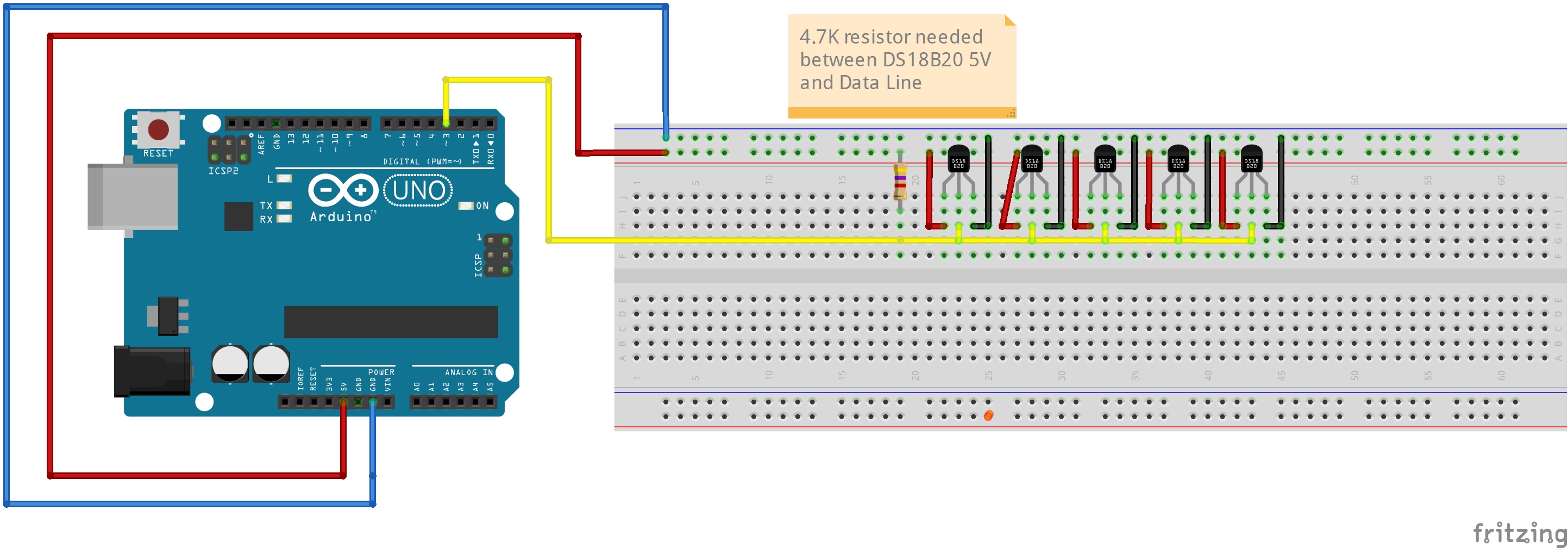
For each of the DS18B20 sensors, they come with color coded wires, red being VCC, black being ground, and yellow being the data line. The benefit of using these sensors is that they can be added to the same data bus without having to add multiple pull up resistors. See here for the data sheet.
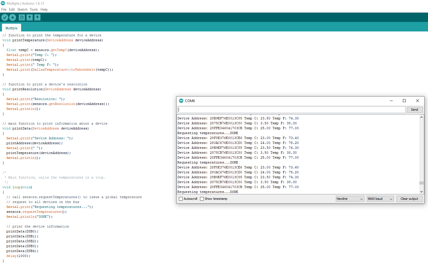
It worked as expected, I was able to read all of the temperatures, however there were a few issues I ran into initially. First off I had some issues reading two of the sensors, but what made that a little difficult is that when I made my code, if any sensors weren’t detected, they would take the serial address of one of the sensors it did find, which made it look like it was still working. With 2 sensors not detected, I had 3 sensors that all read the exact same temperature. It turns out I was missing two wires that prevented two sensors from being seen on the bus.
I don’t like how the code I used just pulled the value of a preexisting sensor that was detected, it masked the fact that two of the sensors weren’t hooked up.
As you can see below on the output, I tested each sensor using a known temperature. My nice cold beer works for this. The remaining sensors are a room temperature, whereas the one in the beer is nice and cold.
In summary:
- Temperature sensors worked as expected
- Need to be mindful of wiring on data bus
- Code needs to flag if a sensor is not working
Sound Testing
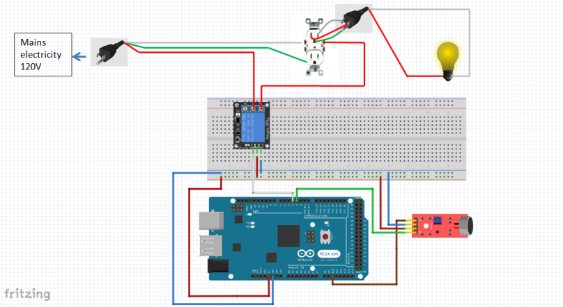
The next test I ran was on the sound sensor. The main goal of this sensor is to monitor if the fire alarm goes off or not. The basic idea is that as long as the sound level is normal, nothing happens. Once the fire alarm goes off, the sound level is much higher than ambient noise. Once this is detected, it opens the relay that’s providing 120V power to the 3D printer. In short, it’s a safety mechanism to kill all electrical power in the event of smoke starting.
I wasn’t able to determine the exact specification of sound sensor module, basically it came in an Elegoo 37 sensor module kit. I believe it’s a KY-038 sound sensor module.
The schematic is pretty simple, there’s 4 outputs from the sensor module. VCC, Ground, Analog Out, and Digital Out.

The sound sensor can output analog voltages, our initial test is just reading what the analog value from the sound sensor. On this sketch, it’s pin A10 we read from. When you read serial analog data off the Arduino, the Arduino outputs a value between 0 to 1023. This is because there’s an analog to digital converter built into the Arduino.
You can plot the analog output on the serial plotter in the Arduino IDE. You can see the ambient noise has an analog value of just above 600, but when I turn on the fire alarm, the sound increases to just above 1000.

In summary, we can see that the sound sensor is working.
Sound Testing – Adding More Functions
While it’s nice to see the sensor is working, I want to start implementing some functionality. Let’s see how we can use the data collected to implement some functions.
As explained above, we want to kill the power to the circuit if the fire alarm goes off. Basically if something is smoking inside the cabinet, we don’t want to feed the fire, we want to kill the electrical power.
What makes this a bit more challenging is that we want to control the behavior of a 120V circuit. Right now we’ve been powering our circuits off the Arduino 5V pin. The big question is, how can we use the Arduino to control higher voltage circuits?
This is where relays come into play. In a simple sense, relays are switches. Basically a lower voltage input can control whether the switch is closed or open. This is handy because we can use the voltage of the Arduino, which is 5V, to open and close a 120V circuit. To learn a lot more about how relays work, see here.
The circuit got a bit more complicated when we introduced the relay, we wired the relay to an outlet and then hooked up the outlet to a light.

I managed to get the circuit working, however I still have some things to figure out about how I cut the power to the circuit. I haven’t quite figured out how to resume the program once I’ve hit the threshold, right now as a quick test I basically had the program terminate once the threshold had been reached. The problem with this method is you have to completely reset the Arduino. While that’s not a huge deal, accessing the Arduino when it’s in the cabinet might be a nuisance, especially if it’s all covered up. Though I’m not planning on this happening all that often, it’s an emergency stop.
In the future I’ll put up a video showing the function when we’re further into building the cabinet.
In summary:
- The sound sensor works
- I need to improve the code to make the program easier to resume or reset without doing a full power cycle.
Next Steps
There are still many tests to run, I have the following functions to check.
- LED Strip Light Function
- Computer Fan Function
- Power Supply Function
- Data Logging Function
- Master/Slave setup of Raspberry Pi and Arduino
Thanks for reading!
